There is an accompanying Picornavirus Monograph Superposition Shell Script that will create PDB files for the models and structural alignments described in this monograph.
Weininger, A.; Weininger, S. (2016)
“Common Features in Picornaviruses, Alpha-bungarotoxin, Myelin P2, and CRABP Suggest
Structural Bases for Multiple Sclerosis, Guillain-Barré Syndrome, and Paralysis Induction”
http://www.weiningerworks.com/picornavirus_monograph.html
Monograph Errata
Table of Contents
- Title
- Authors
- Abstract
- Introduction
- Materials and Methods
- Sequences and Structures
- Sequences Alignment Method
- Structural Alignment Method
- Structural Alignment Of A Representative Set Of VP1234 By Superposing Conserved VP1 Proline Atoms
- Positioning Proteins Onto Icosahedron Faces
- Construction of Picornavirus Model Capsid Tiling Pieces
- Construction of Picornavirus Model Capsids
- Construction of Model Myelin P2 Trimers and CRABP Trimers
- Construction of Model Alpha-bungarotoxin (ABT) Trimers
- Results
- Summary: Picornavirus VP1, VP2, and VP3 Proteins Are Comprised of Myelin P2/CRABP-like and Alpha-Bungarotoxin-like Cores Interrupted By and Separated By Inserts With Specific Viruses Containing The Components of Toxin Domains, Myelin P2 Epitopes, and Sialic Acid Binding Sites
- MP2/CRABP Cores and Central Channel Gating By Helix Two
- Multiple Sclerosis Associated Domain Comprised of Helix One and Helix Two Residues in Specific Picornaviruses
- Structural Compatibility Between Constructed Myelin P2 Trimers And Trimers Of Alpha-Bungarotoxin Dimers; Structural Compatibility Between Myelin P2/CRABP Cores And Toxin Cores
- Loops Common to Toxins Are Found on Mahoney Poliovirus and EV-D68 ET AL.
- Alpha-Bungarotoxin Cores, The Common Toxin Loops, and EV-D68
- Spatially Reconstituted Toxin Loops And The Paralysis Associated Domain
- Sialic Acid Binding Domain in EV-D68
- VP3 Protein Beta Sheets Circling The Pentamer Interface Form The Base Of A Diaphragm Shutter-like Pore
- Using Insert Residue Positions To Isolate Variations in Relative Position of Aligned Structures
- Each Picornavirus Capsid Tiling Piece Has A Myelin-P2 Trimer-like Ion Channel At Its Center
- Discussion
- Supporting Information
- References
- Tables
- Table 1. Abbreviations, reference numbers, sequence and structure sources, description and structure resolutions.
- Table 2. Spatially conserved atoms internal to the VP1 proteins of a representative set of picornaviruses.
- Table 3. Common Spatial Occupancy Group One (CASOG-1) tiling atoms.
- Table 4. Common Spatial Occupancy Group Two (CASOG-2) tiling atoms.
- Table 5. Myelin P2 trimer and CRABP trimer tiling atoms.
- Table 6. Alpha-bungarotoxin and EV-D68 VP1 trimer tiling atoms.
- Table 7. Figure 1 Section locations for each picornavirus Insert.
- Figures
- Figure 1. Aligned sequences of myelin P2, CRABP, alpha-bungarotoxin, and picornavirus VP1, VP2, and VP3 proteins.
- Figure 2. Summary graphic of the aligned sequences of myelin P2, CRABP, alpha-bungarotoxin, and picornavirus VP1, VP2, and VP3 proteins.
- Figure 3. Aligned VP4 sequences.
- Figure 4. Superposition of VP1-VP2-VP3 picornavirus protein assemblies showing CASOG-1 and CASOG-2 orientations.
- Figure 5. Model picornavirus capsid construction for the CASOG-1 and CASOG-2 proteins.
- Figure 6. Comparison of constructed CASOG-1 and CASOG-2 picornavirus capsid tiling piece pentamers.
- Figure 7. Construction of myelin P2 trimers, CRABP trimers, and Alpha-bungarotoxin Trimers.
- Figure 8. Myelin P2, CRABP, and Picornavirus Myelin P2/CRABP Cores.
- Figure 9. Myelin P2 trimers, Alpha-bungarotoxin trimers, Picornavirus Myelin P2/CRABP Cores, and Picornavirus Toxin Cores.
- Figure 10. Toxin Domain Structure in Alpha-bungarotoxin and EV-D68.
- Figure 11. Sialic Acid Binding Domain Components on EV-D68 Capsid.
- Figure 12. Differences in the spatial position of markers in constructed TMEV capsid tiling pieces and capsids.
- Figure 13. VP3 Protein Beta Sheets Circling The Pentamer Interface Form The Base Of A Diaphragm Shutter-like Pore.
- Figure 14. Using Insert Residue Positions To Isolate Variations in Relative Position of Aligned Structures.
- Figure 15. Ion channel-like structure in the center of myelin P2 trimers and VP1 trimers.
Title
Common Features in Picornaviruses, Alpha-bungarotoxin, Myelin P2, and CRABP Suggest Structural Bases for Multiple Sclerosis, Guillain-Barré Syndrome, and Paralysis Induction
Authors
Arthur Weininger
weiningerworks.com
Susan Weininger
weiningerworks.com
Abstract
We found the structural correlates of multiple sclerosis induction and paralysis induction in picornaviruses and proteins. We determined that myelin-P2/CRABP equivalent residues and alpha-bungarotoxin equivalent residues are threaded through the VP1, VP2, and VP3 sequences such that they are mutually exclusive and interrupted by internal and external inserts. We isolated specific proline residues that are sequence invariant in the VP1, VP2, and VP3 proteins and used their placement on the capsid icosahedron face to construct picornavirus capsid models. We present the basis for the hypothesis that picornavirus capsids evolved from cores of myelin P2 and toxin trimers. We have determined that picornaviruses that induce paralysis, such as EV-D68, EV-D70, and Mahoney poliovirus, have loops that are structurally and chemically similar to toxins, such as alpha-bungarotoxin, that induce paralysis. We have determined that specific viruses that induce or are associated with the induction of multiple sclerosis, present residues that are structurally and chemically similar to those presented by myelin P2 helices. In the picornaviruses, we identified what appears to be an ion channel gated by VP1 myelin P2 helices-like residues and also a diaphragm shutter-like pore formed by VP3 pentamers whose VP3 sequence invariant proline stays spatially fixed in the capsid. We identified the components of a sialic acid active site on the EV-D68 capsid.
Introduction
We set as our goal the determination of the structural correlates in the picornaviruses of paralysis and multiple sclerosis induction. Picornaviruses are non-enveloped, positive strand viruses that cause significant disease in animals and humans. The Picornaviradae family includes: Foot and Mouth Disease Virus (“FMDV”) which is not known to induce either paralysis or multiple sclerosis; Theiler's murine encephalomyelitis virus (“TMEV”) which is known to cause multiple sclerosis; the Enteroviruses, which include EV-D68 which is associated with paralysis, Guillain-Barré Syndrome (“GBS”), and multiple sclerosis; and Polioviruses (PV1 or “Mahoney Strain”, PV2 or “Lansing Strain”, and PV3 or “Sabin Strain”) which are known to be associated with paralysis. EV-D68 is an emergent pathogenic picornavirus with expanded tissue preferences and new disease-inducing capability including the induction of irreversible flaccid paralysis in children [1], similar to that seen historically in poliovirus infections. Guillain-Barré Syndrome has been associated with EV-D68 infections, e.g., a cluster of atypical Guillain-Barré Syndrome in ten adults temporally related to a cluster of four children with acute flaccid paralysis from EV-D68 was observed over a 3-month period in Wales [2]. Simply put, EV-D68 and EV-D70 have apparently emerged with TMEV's capacity to induce multiple sclerosis and with the capacity of Mahoney poliovirus (PV1) to induce paralysis.
This study was started with the recognition that a multiple sclerosis-like condition, i.e. demyelination, in mice may be induced either with an infection of TMEV [3] or with an injection of myelin P2 (“MP2”) [4]. Because TMEV infection [3] and MP2 protein injection [4] can cause demyelination and because cellular retinoic acid binding protein (“CRABP”) (1CBS.PDB) [5], is in the same structural family as MP2 (2WUT.PDB) [6], we identified and analyzed the sequence and structural similarities among and the differences between MP2, CRABP, and picornavirus VP1, VP2, and VP3 proteins. Because acute flaccid paralysis can be individually caused by EV-D68, EV-D70, PV1, or specific toxins, we identified and analyzed the sequence and structural similarities among and the differences between a representative toxin that causes paralysis, alpha-bungarotoxin (“ABT”) (Krait snake venom, 2ABX.PDB) [7], and the VP1, VP2, and VP3 proteins of: the Mahoney strain poliovirus (“PV1”) (1HXS.PDB) [8], the Lansing strain poliovirus (“PV2”) (1EAH.PDB) [9], the Sabin strain poliovirus (“PV3”) [10], and an EV-D68 structure (“EV-D68-4WM7”) (4WM7.PDB) [11]. Because EV-D68 has expanded tissue preferences, we looked at whether EV-D68-4WM7 has residues that are spatially presented similarly to residues found in the active site of influenza neuraminidases, such as the influenza N6 neuraminidase (“N6 Neuraminidase”) (1WIX.PDB) [13], that are known to bind to and process sialic acid.
We aligned the sequences of picornavirus VP1, VP2, and VP3 proteins with each other and also with MP2, CRABP, ABT A chain (all residues), and ABT B chain (residues 1 — 48) using a unique alignment method that utilized: a co-grouping of methionine, cysteine, and tryptophan residues; use of glycines and prolines to bracket the sequences; and the use of the MP2, CRABP, and ABT sequences to parse the VP1, VP2, and VP3 sequences. This method of alignment was used to identify prolines that were both spatially conserved and sequence conserved in the VP1, VP2, and VP3 sequences. Atoms in these conserved prolines were used to map the picornavirus VP1234 structures onto an icosahedron in order to build and compare picornavirus capsid models. Atoms in sequence grouped conserved residues were also used to both create model MP2 trimers and CRABP trimers and to superpose these trimers onto all capsid tiling pieces. This allowed us to compare capsid tiling pieces, capsids, MP2 trimers, and CRABP trimers in the same spatial reference frame. We found that picornavirus capsids are comprised of residues in protein segments corresponding to the MP2, CRABP, and ABT sequences and that these segments are separated by well-defined inserts.
We determined that proteins that are associated with the induction of paralysis have common features with the capsids of viruses that are associated with the induction of paralysis and that these features are also common to toxins [12]. We determined that proteins that are associated with the induction of multiple sclerosis (i.e. MP2) have common features with the capsids of viruses that are associated with the induction of multiple sclerosis (i.e., TMEV-1, TMEV-2, and EV-D68) and that these features are located in the sections of sequence that align with the MP2 and CRABP helices. We determined that, for the picornaviruses in our representative set, Foot and Mouth Disease Virus (“FMDV”) (1BBT.PDB) [14] has the fewest residues outside of the MP2/CRABP-like and ABT-like sequence groupings, that FMDV VP1, VP2, and VP3 protein sequences are the least similar to other picornavirus VP1, VP2, and VP3 protein sequences, and that FMDV has no features consistent with the induction of either paralysis or multiple sclerosis.
Placement of atoms from the sequence conserved prolines in VP1, VP2, VP3, and VP4 protein assemblies (“VP1234”) onto specific points on the faces of a 135 Angstrom-on-a-side icosahedron produced capsid models for the twenty picornaviruses in the sample set. For each VP1234, there are nine points on an icosahedron face that can be used to position three VP1234 assemblies (“3xVP1234”) to complete a model capsid tiling piece. Three of these points representing VP3 atom positions are on the edges of the capsid icosahedron. Twenty model capsid tiling pieces in the shape of an icosahedron form the constructed capsid models. In each VP1234, the residues of the VP1, VP2, and VP3 protein assembly (“VP123”) are exposed to the outside of the capsid (“OUTER”). The VP4 residues are exposed to the inside of the capsid (“INNER”). The INNER VP4 proteins interact directly with the viral RNA on the inside of the capsid. It is known that mature picornavirus particles bind to receptors, leading to the release of the N-terminus of VP1 [15] and VP4 [16] which forms a 135S intermediate called an “A particle”. The A particle is endocytosed [17] and delivers the RNA to the host cell. The VP1 protein has been shown to be partially extruded from the capsid during uncoating [18].
Examination of the spatial relationship between the conserved proline atoms in VP123 and the constructed capsid models showed that VP123 structures fall into two structural groups: common atomic structure occupancy group one (“CASOG-1”) and common atomic structure occupancy group two (“CASOG-2”). CASOG-1 and CASOG-2 differ in the relative positions of two of the conserved prolines in VP123, the VP1 and VP2 conserved prolines. The VP3 conserved proline is in the same position in CASOG-1 and CASOG-2. The VP3 protein positions are pivoted about the VP3 conserved proline. Since two different TMEV VP1234 structures were found with nearly identical sequence: “TMEV-1” (1TME.PDB) [19] in CASOG-1 and “TMEV-2” (1TMF.PDB) [20] in CASOG-2, we interpreted the difference in the VP1234 structure positions in the TMEV-1 and TMEV-2 constructed capsids as a permitted, relative motion of proteins within the capsids of picornaviruses as a class. In TMEV-1 and TMEV-2 capsid models, we identified diaphragm shutter-like pores at picornavirus capsid vertices, i.e., at the center of five VP3 proteins presented by a pentamer of five capsid tiling pieces. The five VP3 proteins lining the pore have positions that are rotated about the sequence and structurally invariant VP3 prolines. A comparison of the TMEV-1 and TMEV-2 structures suggests that the A particle can exit through a diaphragm shutter-like pore by a change in the position of VP3 relative to VP1 and VP2. The two positional endpoints are seen in the TMEV-1 and TMEV-2 constructed capsid models.
Atoms in MP2 monomers, CRABP monomers, and ABT dimers were superposed onto specific VP123 atoms in the model capsid tiling pieces to create model: MP2 trimers, CRABP trimers, and trimers of ABT dimers. The specific atoms used to create the model trimers of MP2, CRABP, and ABT are from structurally important sequence conserved residues in MP2, CRABP, and ABT. The constructed MP2 trimers, CRABP trimers, and trimers of ABT dimers are co-located with VP1234 trimers in the capsid tiling pieces. Co-location of the trimers (picornavirus VP1234, MP2, CRABP, and ABT dimer) allowed us to identify the existence of, and the basis for the function and gating of, an ion channel at the center of picornavirus capsid faces, i.e., at the center of tiling pieces. This co-location of the trimers allowed us to examine the relationship between this ion channel and VP4 proteins that anchor the viral RNA. From the comparative analysis of MP2 trimers, CRABP trimers, and picornavirus VP1 trimers, we suggest the structural basis for ion channel function and dysfunction.
The sequence alignment of ABT chains A (all residues) and B (residues 1 — 48 only) with VP1, VP2, and VP3 proteins was used to identify residues from picornavirus proteins that may historically have been derived from ABT and are still present in all picornaviruses. We also looked in picornaviruses for toxin loop residues that are common to specific protein toxins (“TOX DOMAIN”, i.e., the residues listed in Table 9 (local link) of Reference [12] and shown in Figure 12 (local link) of Reference [12]), e.g., ABT, staphylococcal enterotoxin I, botulinum toxin, anthrax lethal factor, tetanus toxin, and an emergent influenza virus (H18N11) [12]. We found TOX DOMAIN loop residues in the structures of Mahoney poliovirus, PV1 [10], and in EV-D68 [11]. In PV1 and in EV-D68, these TOX DOMAIN loop residues are in ABT sequence aligned positions and separately are also in an insert (“INSERT LOOP”) that is not ABT sequence aligned (i.e., outside of the ABT threading). The spatial positions of the PV1 INSERT LOOP residues is similar to what would be expected if the PV1 INSERT LOOPS were derived from residues that were sequence aligned with ABT. If EV-D68-4WM7 had the same sequence as the pathogenic EV-D68 and if all of the positions of the EV-D68 INSERT LOOP residues were shown, then the spatial positions of the EV-D68 INSERT LOOP residues would be similar to what would be expected if all ABT chain B residues, including residues 49 — 74, had been included historically in all picornavirus VP1, VP2, and VP3 sequences. The EV-D68 TOX DOMAIN loops were derived from residues that were sequence aligned with ABT residues and from residues that have been added in non-Toxin Core segments of VP1 and VP2, including in the Insert sequences. The INSERT LOOP of EV-D68-4WM7 has flanking residues missing from the crystal structure, has critical residues (e.g., H87) different from other pathogenic EV-D68 sequences (e.g., D87), and presents groups in close contact with bound plecornaril (e.g., L220). Despite the difference in sequence between the EV-D68-4WM7 VP1 proteins and pathogenic EV-D68 proteins, and despite the absence of flanking residues in the EV-D68-4WM7 INSERT LOOP, the constructed capsid allowed us to isolate the position of pathogenic EV-D68-4WM7 INSERT LOOP residues, compare the EV-D68-4WM7 INSERT LOOP residues to PV1, and relate the EV-D68 TOX DOMAIN residues to the positions of bound plecornaril. In the EV-D68-4WM7 crystal structure, we also found a structural feature with the components of a sialic acid-binding site (“SIA SITE”, shown in Figure 2 (local link) of Reference [12]) largely positioned adjacent to the TOX DOMAIN. The EV-D68 SIA SITE and the EV-D68 TOX DOMAIN overlap by sharing a residue.
From the co-located trimers, we identified structural features presented on EV-D68 and PV1 that are also present in MP2, CRABP, and ABT. From an analysis of these common structural features, we generated a hypothesis regarding the structural basis for the induction of acute flaccid paralysis. We hypothesize that viruses with TOX DOMAINS can bind to acetylcholine receptors. We hypothesize that acute flaccid paralysis is caused by specific picornavirus capsid engagement of acetylcholine receptors and that this is the event that causes permanent loss of ACH receptor patches in the junction between motor neurons and muscle. We hypothesize that mutations in EV-D68 or EV-D70 will be seen in residues at positions that either contact plecornaril (or similar molecules) and/or will be seen in residues that contact or impact TOX DOMAIN residues. We suggest that the EV-D68 site with neuraminidase active site binding components binds sialic acid, and that the binding of small molecules to this site may compete with acetylcholine receptor binding by EV-D68.
We identified a common structural feature in MP2 helices, CRABP helices, and in specific picornavirus VP1 residues including TMEV, EV-D68, EV-D70, and EV-D94. We hypothesize that multiple sclerosis is induced when this common structural feature is presented to the immune system as an epitope (“MS Epitope”). We hypothesize that induction of multiple sclerosis by emergent viruses (e.g., EV-D68 (including HRV-87), EV-D70, and EV-D94) and by historical viruses (e.g., TMEV) occurs when the MS Epitope on the picornavirus capsid is exposed due to defective viral uncoating. In EV-D68, EV-D70, and EV-D94, the exposure of this epitope may be related to the engagement of the acetylcholine receptors by these viruses using their toxin-like domains so that the epitope is exposed upon viral uncoating.
The combination of a parsed, comprehensive sequence alignment and complete capsid models provides the context for capsids to be searched for domains and functional structures, regardless of whether the structural domain exists within a single protein or spans multiple proteins. We have identified structures with functional implications that are ABT-like domains, ion channels, pores, MP2/CRABP helices-like domains, and sialic acid binding components. Examination of these characterized capsid components allowed us to specifically hypothesize: how the entire capsid is constructed and functions for picornaviruses as a class; the structural foundation of and the related functional basis for the induction of multiple sclerosis by Theiler's Viruses and EV-D68; the structural foundation of and the related functional basis for the induction of Guillain-Barré Syndrome and acute flaccid paralysis by EV-D68 and Mahoney strain polioviruses; the structural foundation of and the related functional basis for sialic acid binding by EV-D68; the structural foundation and related functional operation of MP2 as a gated ion channel; and the structural foundation and related functional operation of ABT and ABT-like toxins. This study provides an analytic procedure for understanding the structural context of expanded tissue preferences and pathology in historical and emergent viruses.
Materials and Methods
Sequences and Structures
Abbreviations, reference numbers, sequence sources, structure sources, and resolutions of the X-ray crystal structures used in the analysis are listed in Table 1. Sequences and structures of CRABP (1CBS.PDB) [5], myelin P2 protein (“MP2”) (2WUT.PDB) [6], and alpha-bungarotoxin dimer (“ABT”) (2ABX.PDB) [7] were aligned with representative picornavirus VP1, VP2, and VP3 proteins: Aphthovirus Foot and Mouth Disease Virus (“FMDV”) (1BBT.PDB) [14]; Cardiovirus Theiler's Murine Encephalomyelitis Virus (“TMEV-1”) (1TME.PDB) [19] and (“TMEV-2”) (1TMF.PDB) [20]; Enterovirus A species EV-A71-1 (3VBH.PDB) [21] and EV-A71-2 (4CEW.PDB) [22]; Enterovirus B species coxsackieviruses EV-B-CV-A9 (1D4M.PDB) [23] and EV-B-CV-B3M (1JEW.PDB) [24]; Enterovirus B species echovirus 7 EV-B-ECHOV-7 (1M11.PDB) [25]; Enterovirus B species Swine Vesicular Disease Virus, EV-B-B5-SVDV (1OOP.PDB) [26]; Enterovirus C species polioviruses EV-C-PV1-M (“Mahoney strain”) (1HXS.PDB) [8], EV-C-PV2-L (“Lansing strain”) (1EAH.PDB) [9], and EV-C-PV3-S (“Sabin strain”) (1PIV.PDB) [10]; Enterovirus C species coxsackieviruses EV-C-A21 (1Z7S.PDB) [27] and EV-C-A24 (4Q4Y.PDB) [28]; Enterovirus D species EV-D68-4WM7, (4WM7.PDB)[10]; Enterovirus G species bovine virus EV-G5-27 (1BEV.PDB) [29]; Rhinovirus A species HRV-A2 (1V9U.PDB) [30] and HRV-A16 (1AYM.PDB) [31]; and Rhinovirus B species HRV-B14 (1D3I.PDB) [32]. Also analyzed were sequences for Enterovirus B species coxsackieviruses EV-B-CV-B1-1 [33], EV-B-CV-B1-2 [34], EV-B-CV-B1-3 [35], EV-B-CV-B3 [36], EV-B-CV-B6 [37], Enterovirus C species coxsackievirus EV-C-CV-105 [38], Enterovirus D species EV-D68-CH14 [39], EV-D68-JP11 [40], EV-D68-NZ13 [41], EV-D68-SW07 [42], EV-D68-US14-1 [43], EV-D68-US14-2 [44], EV-D70-UK09 virus [45], EV-D94-FN07 [46] and a rhinovirus reclassified as an Enterovirus D species HRV-87-US04 [47]. The VP4 sequence for Echovirus 7 was obtained from GENBANK (AAK85711.1 [48]) as the 1M11.PDB structure did not contain a VP4 sequence.
Sequence Alignment Method
Bracketing Glycines and Prolines, Residue Grouping
In Figure 1 and in Figure 3, glycines (G) and prolines (P) in all sequences were placed on homogeneous columns flled with either glycines or prolines. These residues were used to “bracket” other residues in the sequences whether or not these residues were in any one sequence. The following sets of residues are grouped into columns, and residues within each set were considered identical for column positioning:
- (a) alanine (A), phenyalanine (F), isoleucine (I), leucine (L), valine (V), and tyrosine (Y);
- (b) cysteine (C), methionine (M), and tryptophan (W) residues;
- (c) aspartic acid (D) and glutamic acid (E);
- (d) histidine (H), lysine (K), and arginine (R);
- (e) asparagine (N) and glutamine (Q); and
- (f) serine (S) and threonine (T).
Residues bracketed between glycine (G) and proline (P) columns were brought into alignment to maximize the exact column alignment of identical residues in the column when possible. When there was not enough information to place a residue in one column versus another in an area between the glycines (G) and prolines (P), a column was selected to enhance exact residue alignment and visual grouping of residues. Examples of possible alternate sequence alignments of residues were indicated with hyphens and greater-than/less-signs, e.g. “––>” and “<––”.
Using Reference Sequences MP2, CRABP, and ABT to Align Picornavirus Sequences
Figure 1 shows the picornavirus sequences of VP1, VP2, and VP3 aligned with each other and also with the reference sequences MP2, CRABP, and ABT. This alignment and isolated features are summarized in Figure 2 with a copy of Figure 2 embedded at the bottom right of Figure 1 for easy reference. Figure 3 shows picornavirus sequences of VP4 residues aligned with each other. Correspondence with the index sequences (MP2, CRABP, and ABT) was visually enhanced by coloring the entire column, and also positionally equivalent columns, with the background color of the index sequence residues as given in the Figure 1 legends. These sequences are divided into sections based on sequence correspondence with the reference sequences. In Figure 1, picornavirus sequences that have correspondence with: MP2/CRABP are found in or aligned with yellow and red Sections M1 — M16; ABT chain A are found in or aligned with magenta Sections A1 — A6; and ABT chain B are are found in or aligned with cyan Sections B1 — B5. In Figure 1, sequences that have no sequential correspondence with either MP2/CRABP or the ABT chains A and B are found in sections marked as insertions. The insertions are grouped and colored as to whether they only occur in VP1 (dark blue Sections I1), only occur in VP2 (green Sections I2), only occur in VP3 (tan Sections I3), or if they occur in more than one or in all VP1, VP2, and VP3 sequence sections (purple Sections I13, I23, and I123). Figure 2 reflects these Figure 1 highlight colors as background colors for the lines representing the reference sequences, and as background colors for the insertion suffix numbers representing positions in the groupings that are not related to the reference sequences. Figure 1 sections that contain either toxin features or markers have subsection titles that include descriptive suffixes: “-T” for natural toxin residues that occur in ABT chain A or B; “-ST” for added toxin residues that are common to toxins but are either outside of the Toxin Cores or have been repurposed to a new toxin loop; “-SW” for sialic acid binding/sialidase binding pocket components; “-SP” for residues contacting the sialic acid in the 4Q4Y.PDB structure; and “-M” for residues used as markers for TMEV-1 and TMEV-2 to show their relative VP1234 internal positions of VP1, VP2, and VP3.
Structural Alignment Method
Structural Alignment Of A Representative Set Of VP1234 By Superposing Conserved VP1 Proline Atoms
In order to examine the structural variation in the relationship between the VP1, VP2, VP3, and VP4 proteins in the picornavirus VP1234 protein assemblies in our representative set, we first oriented the VP1234 for each picornavirus using residues internal to one protein, VP1. The atoms listed in Table 2 were superposed to determine the structural variation in the VP1234 when the VP1 proteins are superposed. The positions of the conserved prolines whose main chain oxygens are listed in Table 2 are indicated in Figure 1 by the “@” symbol in the VP1 section header above the proline columns. These Figure 1 positions occur: between Sections M-11 and I13-2; between Subsections 3 and 4 of Section A-1; and between Subsections 8 and 9 of Section M-14. The positions of the conserved prolines whose main chain oxygens are listed in Table 2 are indicated in Figure 2 by the “@” symbol in the grey picornavirus protein threading line. The VP1234 structures that were superposed using VP1 internal prolines are shown in Figure 4 column 1. We determined that the VP1234 structures fell into two Common Atomic Spatial Occupancy Groups: CASOG-1 (18 structures) and CASOG-2 (2 structures). All but two structures, the two CASOG-2 structures FMDV (1BBT.PDB) and TMEV-2 (1TMF.PDB), have nearly identical VP1234 internal orientation. Because TMEV-1 and TMEV-2 have nearly the same sequence, they represent demonstrated VP1234 internal structural variation.
Positioning Proteins Onto Icosahedron Faces
In order to examine the structural variation in the relationship between the VP1, VP2, VP3, and VP4 proteins in the picornavirus capsids in our representative set, we placed VP1234 assemblies onto specific locations on a model capsid face using atoms in conserved prolines. Three specific atoms were used for each VP1234 placement, one each from VP1, VP2, and VP3 proteins. Tables 3 and 4 lists these atoms, which are main chain oxygens from conserved prolines. These prolines are sequence invariant within each protein and structurally invariant within CASOG-1 and within CASOG-2. In Figure 1, the sequence positions of these conserved prolines are indicated by '*' symbols shown both in the section headers on top of these conserved proline columns as well as in columns flanking these conserved proline columns. In Figure 1, these conserved prolines are between Sections M-11 and I13-2 for VP1 and VP2 and are between Sections B-3 and B-4 for VP3. In Figure 2, the positions of these conserved prolines are indicated by the '*' symbol in the grey picornavirus protein threading line.
To facilitate construction of picornavirus model capsid tiling pieces, MP2 trimers, and CRABP trimers, we created sets of idealized points that represent specific atom destination positions located on the face of an icosahedron. A complete set of idealized points for creating picornavirus capsid tiling pieces, MP2 trimers, and CRABP trimers is provided as representative atoms in supporting information file PICORNAVIRUS_TILING_POINTS.PDB (“PICORNAVIRUS TILING POINTS”). Picornavirus, MP2, and CRABP proteins were placed in specific geometries on an icosahedron face by superposing three specific protein atoms with three specific points in PICORNAVIRUS TILING POINTS. These superpositions do not change the relative positions of the atoms within MP2 or CRABP, nor do they change the relative positions of the atoms within each picornavirus VP1234 assembly. For visual reference, two sets of idealized points are provided as supporting information files: ICOS135.PDB (“ICOS135”) and TRI78.PDB (“TRI78”). ICOS135 contains points at the vertices of a 135 Angstrom-on-an-edge icosahedron, the icosahedron representing the picornavirus capsid face. TRI78 contains points at the vertices of 78 Angstrom-on-a-side equilateral triangles that are positioned with their vertices on ICOS135 icosahedron edges and 45 (and 90) Angstroms away from the ICOS135 icosahedron vertices. PICORNAVIRUS TILING POINTS are all located on or within the first listed triangle in TRI78, which is within the first ICOS135 listed triangle (i.e., the first listed icosahedron face).
Construction of Picornavirus Model Capsid Tiling Pieces
Models of picornavirus capsid tiling pieces (i.e., 3xVP1234 picornavirus capsid tiling pieces) were constructed by separately placing three VP1234 structures onto an icosahedron face. Individual VP1234 structures were placed by superposing three specific VP1234 conserved proline atoms onto specific icosahedron face points. Models of CASOG-1 picornavirus VP1234 trimers (i.e., 3xVP1234 picornavirus capsid tiling pieces) were constructed by three superpositions of the atoms in the rows of Table 3 with consecutive PICORNAVIRUS TILING POINTS having the chain identifier “1” (e.g., the TMEV-1 (1TME.PDB) atoms listed in Table 3 were superposed onto consecutive PICORNAVIRUS TILING POINTS 1, 2, 3, then again onto 4, 5, 6, and lastly onto 7, 8, 9). Models of CASOG-2 picornavirus VP1234 trimers (i.e., 3xVP1234 picornavirus capsid tiling pieces) were constructed by three superpositions of the atoms in the rows of Table 4 with consecutive PICORNAVIRUS TILING POINTS having the chain identifier “2” (e.g., the TMEV-2 (1TMF.PDB) atoms listed in Table 4 were superposed onto consecutive PICORNAVIRUS TILING POINTS 11, 12, 13, then again onto 14, 15, 16, and lastly onto 17, 18, 19).
The CASOG-1 and CASOG-2 model capsid tiling pieces constructed for our representative set of picornaviruses can be seen in Figure 4. Figure 4 columns 2 — 6 show trimers of VP1234, VP1, VP2, VP3, and VP4, respectively. A different picornavirus is shown in each row of Figure 4: 1AYM (B), 1BBT (C), 1BEV (D), 1D4M (E), 1EAH (F), 1HXS (G), 1OOP (H), 1PIV (I), 1TME (J), 1TMF (K), 1V9U (L), 1Z7S (M), 3VBH (N), 4CEW (O), 4Q4Y (P), and 4WM7 (Q). An examination of Figure 4 rows C and K show the two CASOG-2 structures, FMDV (1BBT.PDB) and TMEV-2 (1TMF.PDB), which differ in the VP1234 orientation.
The process of creating the CASOG-1 and CASOG-2 model capsid tiling pieces and capsids is illustrated in Figure 5. Figure 5 Panel A shows both CASOG-1 and CASOG-2 tiling points on a single TRI78 triangle. The vertices of the TRI78 triangles are points that represent positions of conserved VP3 proline atoms in both CASOG-1 and CASOG-2 picornavirus capsids. The VP3 atoms in Tables 2 — 4 are both sequence conserved and spatially conserved. In Figure 5, the VP1 CASOG tiling points are colored cyan, the VP2 CASOG tiling points are colored green, and the VP3 CASOG tiling points are colored yellow. Figure 5 Panels B, D — F show CASOG-1 VP123 positions, i.e., the destination points for individual CASOG-1 VP1, VP2, and VP3 atoms listed in Table 3. Figure 5 Panels G — I show individually placed TMEV-1 VP1234 proteins. Figure 5 Panels P and S show the completed TMEV-1 capsid tiling pieces, i.e., placed CASOG-1 3xVP1234. Figure 5 Panels C, J — L show CASOG-2 VP123 positions, i.e., the destination points for individual CASOG-2 VP1, VP2, and VP3 atoms listed in Table 4. Figure 5 Panels M — O show individually placed TMEV-2 VP1234 proteins. Figure 5 Panels Q and T show the completed TMEV-2 capsid tiling pieces, i.e., placed CASOG-2 3xVP1234. Figure 5 Panels R and U show the completed TMEV-1 (CASOG-1) superposed with the nearly sequence identical TMEV-2 (CASOG-2) 3xVP1234 tiling pieces.
Construction of Picornavirus Model Capsids
Models of picornavirus capsids were created with sixty separate placements of VP1234 structures onto an icosahedron. Each of these VP1234 placements was made with the superposition of three specific conserved proline atoms (listed in Tables 2 and 3) onto a set of three idealized points provided as one triplet of consecutive atoms (e.g., 1,2,3; or 4,5,6; etc. through 178,179,180) in either supporting information file CASOG_ONE_CAPSID_POINTS.PDB for CASOG-1 structures or supporting information file CASOG_TWO_CAPSID_POINTS.PDB for CASOG-2 structures. Each tiling piece of the resultant capsids has the appropriate CASOG-1 and CASOG-2 geometry illustrated in Figure 4 and in Figure 5. The overall structural features of CASOG-1 and CASOG-2 capsids are shown by representative tiling piece pentamers in Figure 6. Figure 6 column 1 Panels A, D, G, and J separately show INNER and OUTER views of the residue spheres and cartoons of a pentamer of TMEV-1 (CASOG-1) capsid tiling pieces. Figure 6 column 2 Panels B, E, H, and K separately show INNER and OUTER views of the residue spheres and cartoons of a pentamer of TMEV-2 (CASOG-2) capsid tiling pieces. Figure 6 column 3 Panels C, F, I, and L show the composite of structures and residues shown in columns 1 and 2.
Construction of Model Myelin P2 Trimers and CRABP Trimers
Models of myelin P2 trimers and CRABP trimers were constructed by three superpositions of the atoms in the rows of Table 5 with consecutive PICORNAVIRUS TILING POINTS having the chain identifier “3”. Figure 7 Panel A shows the relationship between CASOG tiling points and myelin P2/CRABP trimer points. Three of these destination points map directly onto TMEV-1 atoms, three map onto TMEV-2 atoms, and three map onto idealized points on the face of the icosahedron such that the myelin P2/CRABP and TMEV-2 Figure 1 Section M-2 Subsection 3 residues are in spatial alignment. Table 5 lists the three myelin P2 (2WUT) atoms and the three CRABP (1CBS) atoms that were separately used to construct myelin P2 and CRABP trimers from three superpositions of their individual monomers. (e.g., the myelin P2 atoms listed in Table 5 were superposed onto consecutive PICORNAVIRUS TILING POINTS 21, 22, 23, then again onto 24, 25, 26, and lastly onto 27, 28, 29). The iterative superpositions of the Table 5 atoms onto the PICORNAVIRUS TILING POINTS are illustrated in Figure 7 Panel B. The resultant myelin P2 trimers are shown positioned on an icosahedron face as shown in Figure 7 Panels C and D. The resultant CRABP trimers, made by the same process as the myelin P2 trimers, are shown with the myelin P2 trimers in Figure 7 Panel D. This process co-locates constructed picornavirus trimers (3xVP1234), myelin trimers, and CRABP trimers so that a comparison of the molecular structural anatomy can be performed.
Construction of Model Alpha-bungarotoxin (ABT) Trimers
Trimers of ABT dimers were created by superposing ABT chain A atoms in the ABT dimer (2ABX.PDB) onto EV-D68-4WM7 VP1 trimer atoms (4WM7.PDB), where both sets of atoms are specified in Table 6. The atoms in Table 6 are present in the ABT and EV-D68-4WM7 sequence aligned residues in Figure 1 Section A1 Subsections 3, 6, and 7. Using this method, trimers of ABT dimers (chains A and B) are created that will be co-located with the MP2 trimers, the CRABP trimers, and all picornavirus VP1234 trimers in the capsid tiling pieces. Figure 7 Panel E shows cartoons of a trimer of ABT in its superposed position and the ABT Table 6 atoms as spheres. Figure 7 Panel F shows cartoons of the EV-D68 VP1 trimer Toxin Section Residues and the EV-D68 VP1 Table 6 atoms as spheres. Figure 7 Panel G shows cartoons of a trimer of ABT in its superposed position, the EV-D68 VP1 trimer Toxin Section Residues overlapping the corresponding ABT A chain cartoon, and all of the Table 6 atoms as spheres. Figure 7 Panel H shows that the optimal alignment of all three ABT atoms with all three EV-D68 VP1 trimer atoms in Table 6 also produces a perfect overlap at the center of the trimers of ABT atom 91 with EV-D68 atom 1414; and ABT atom 96 with EV-D68 atom 1412; which can be used as an additional check on positioning the ABT trimer.
Results
Summary: Picornavirus VP1, VP2, and VP3 Proteins Are Comprised of Myelin P2/CRABP-like and Alpha-Bungarotoxin-like Cores Interrupted By and Separated By Inserts With Specific Viruses Containing The Components of Toxin Domains, Myelin P2 Epitopes, and Sialic Acid Binding Sites
As can be seen from Figure 1 and Figure 2, we have determined that picornavirus capsids are comprised largely of separate myelin P2/CRABP-like sequences (“MP2/CRABP Cores”- Figure 1 Sections M-1 to M-16 (i.e. M-1, M-2, … , M-16)) and alpha-bungarotoxin-like sequences (“Toxin Cores” - Figure 1 Sections A-1 to A-6 (i.e., A-1, A-2, … , A-6) and B-1 to B-5 (i.e., B-1, B-2, … , B5)) interrupted by and separated by residues that are labelled as “Inserts.” Table 7 lists Figure 1 section locations for each of these inserts. The MP2/CRABP Cores, Toxin Cores, and Inserts are mutually exclusive and clustered into domains whose attributes are described below. The positions of the Inserts between the VP1, VP2, and VP3 proteins is not random. For example, it can be seen from an examination of Figure 2 that Inserts that are seen in VP1 only (VP1 ONLY INSERT I1-#) are embedded only in the ABT Cores. Figure 3 shows the VP4 proteins sequences that we aligned. The VP4 sequences are highly related to each other but unrelated to the MP2/CRABP Cores and Toxin Cores. The Figure 1 alignment allowed us to relate Insert sequences and associated structures with the functions that were added to the MP2/CRABP Cores and Toxin Cores to produce the functioning viral capsid. Understanding where the MP2/CRABP Cores, Toxin Cores, and Inserts are located in the sequence and located in the structure helped us to isolate the structural correlates of pathogenicity in specific picornaviruses, including TMEV, Mahoney poliovirus PV1, EV-D68, and EV-D70.
MP2/CRABP Cores and Central Channel Gating By Helix Two
Myelin P2 and CRABP constructed trimers present residues that occupy a similar bulk volume to VP1 MP2/CRABP Cores. Figure 8 Rows A and B show OUTER and INNER views of trimers of: CRABP (Panels A0 and B0), myelin P2 (Panels A1 and B1); FMDV VP1 (Panels A2 and B2); TMEV-2 VP1 (Panels A3 and B3); TMEV-1 VP1 (Panels A4 and B4); PV1 VP1 (Panels A5 and B5); and EV-D68 VP1 (Panels A6 and B6). In Figure 8, the MP2/CRABP Core residues corresponding to Figure 1 Sections M-1 to M-16 are colored yellow with the exception that residues in Section M-2 and M-3 (MP2/CRABP “Helix One”) are colored red and M4 (MP2/CRABP “Helix Two”) are colored dark red in order to emphasize the variation in the position of these residues. TMEV-1 and TMEV-2 have nearly the same sequence but exhibit differences in the relative positions of their VP1, VP2, VP3, and VP4 MP2/CRABP Cores. We suggest that the TMEV-1 and TMEV-2 structural differences reflect endpoints of a structural reorientation of VP1, VP2, and VP3 residues within the VP1234 and that these VP1234 configurations can be interpreted as permitted, relative motion in the capsid, including, but not limited to, the relative positions of Helix One and Helix Two.
It can be seen from an examination of Figure 8 Row B (Panels B1 — B7) that Helix Two residues can take up positions that vary from being radially distant to being concentrated at the center of the trimers (“Central Channel”). Rows C (Panels C2 — C6) and D (Panels D2 — D6) show the OUTER and INNER views of VP2 MP2/CRABP Cores and their residue positions varying from being radially distributed to being concentrated about the Central Channel. Rows E (Panels E2 — E6) and F (Panels F2 — F6) show the OUTER and INNER views of the VP3 MP2/CRABP Cores showing the positions of the VP3 MP2/CRABP Core residues pivot about the VP3 atoms in Tables 3 and 4. Rows G (Panels G2 — G6) and H (Panels H2 — H6) show the OUTER and INNER views of the VP1, VP2, and VP3 MP2/CRABP Cores showing that the VP123 MP2/CRABP Cores cover most of the capsid tiling piece and that the spatial relationship between the VP1, VP2, and VP3 Helix One and Helix Two residues can exist in completely radially distributed forms to radially concentrated forms in the constructed capsids.
Multiple Sclerosis Associated Domain Comprised of Helix One and Helix Two Residues in Specific Picornaviruses
N-terminal residues in the VP1 sequences of specific picornaviruses, located in Figure 1 Sections M2 — M4 (Helix One and Helix Two), appear to be able to form a domain which is associated with the capacity to induce multiple sclerosis, i.e., the feature is present in viruses and other proteins known to induce or to be associated with multiple sclerosis. The MS-associated feature is found in myelin P2, TMEV, and pathogenic EV-D68 ET AL. The feature, the putative MS Epitope, includes the presentation of DD and EE residues in M-2 Subsection 1 or in M-2 Subsection 3 (whether presented side-by-side in the sequence or structurally side-by-side in the helix), a K or R residue in M-3, and NQ residues in M-4 Subsection 2.
Structural Compatibility Between Constructed Myelin P2 Trimers And Trimers Of Alpha-Bungarotoxin Dimers; Structural Compatibility Between Myelin P2/CRABP Cores And Toxin Cores
The structural compatibility between: a) constructed Myelin P2 trimers and trimers of alpha-bungarotoxin dimers; and b) selected picornavirus VP1 Myelin P2/CRABP Cores and Toxin Cores can be seen in Figure 9. Panels A and B show that the constructed Myelin P2 trimers fit well with constructed trimers of alpha-bungarotoxin dimers. Figure 9 Panels C — L shows that this compatibility is maintained in the picornavirus VP1 Myelin P2/CRABP Cores and Toxin Cores of FMDV, TMEV-2, TMEV-1, PV1, and EV-D68. The variation in internal and external contacts within the Myelin P2/CRABP Cores and Toxin Cores can be utilized to understand the structural variation internal to and external to (i.e., in relationship to the rest of the capsid) the VP1 Myelin P2/CRABP Cores and Toxin Core residues. It can also be used to determine whether features present on trimers of alpha-bungarotoxin dimers, largely missing in the picornaviruses due to the lack of threading of any ABT chain B residues 49 — 74 in the VP1 proteins, have been reconstituted and presented on emergent viruses that cause paralysis.
Although picornaviruses all have Toxin Cores (Figure 1 Sections A-1 to A-6 and B-1 to B-5), only the residues 1 — 48 of the ABT B chain are threaded in the VP1, VP2, and VP3 proteins. For this reason, only a subset of the loops that are presented by alpha-bungarotoxin dimers are presented by the Toxin Cores on the capsid surface. Because of the absence of the residues that would correspond to the C-terminal residues of ABT chain B, picornaviruses as a group have not maintained all the loop sequences necessary to form a toxin-like domain associated with a protein assembly's ability to engage acetylcholine receptors on their capsids.
Loops Common to Toxins Are Found on Mahoney Poliovirus and EV-D68 ET AL.
We identified TOX DOMAINS formed from ABT-like loops from residues both within the Toxin Cores and outside of the Toxin Cores. Figure 1 shows the locations of distributed residues in the sequences of specific viruses that appear to be able to form a domain which is associated with the capacity to induce paralysis, i.e., the feature is present in toxins and viruses (and specific closely related viruses) known to induce paralysis. Loop residues in the ABT A chain and partial B chain present in the VP1 Toxin Cores are designated by “-T” in Figure 1 and are found in Figure 1 Sections: B4 Subsections 1 and 2; B5 Subsection 1, A-1 Subsections 6, 7, and 9; A-3 Subsections 1 and 2; and A-2 Subsections 1 and 2. These residues are shown in Figure 2 on the row labelled “ALPHA BUNGAROTOXIN LOOP RESIDUES.” Loop residues outside the Toxin Cores or outside of VP1 that present to spatial positions that are similar to positions of ABT common toxin residues in the complete superposed trimer of ABT dimers but that are missing from the VP1 Toxin Cores (“SPATIALLY RECONSTITUTED TOXIN LOOPS”) are designated by “-ST” in Figure 1 and are found in Figure 1: PIV1, EV-D68 ET AL. VP1 Section I-1 Subsection 1 and Section I1-2 Subsections 3 and 4; PIV1 VP1 Sections M-12 Subsections 1 and 2; and EV-D68 ET AL. VP2 Section A-3 Subsection 2.
Alpha-Bungarotoxin Cores, The Common Toxin Loops, and EV-D68
The superposition of alpha-bungarotoxin residues on their corresponding EV-D68 VP1 residues allowed us to make construct a model trimer of ABT dimers. This produced several interesting results. We previously identified loop residues common to several toxins [12], including ABT, anthrax lethal factor, botulinum toxin, clostridium toxin, and staphylcoccal enterotoxin I. It was not until we superposed the ABT atoms on the corresponding EV-D68 atoms to make the ABT trimers that it became clear what role the residues in the conserved loops play in the toxin structure. Figure 10 Panel A shows the constructed ABT trimer and the residues in ABT that are relatively common to toxins. Figure 10 Panel B shows that two of the conserved ABT A chain loops (GENLC and TDKN) form an tight annulus of complimentary charge with the other two loops (YEE and DGF) taking up a position opposite one another such that the TYR and PHE residues can interact. This configuration would act to lock the trimer A chain annulus into position, presenting another set of toxin loops from the B chain. Since only the ABT chain B residues 1 — 48 are threaded in the VP1, VP2, and VP3 sequences, key loops engaged in the binding of acetylcholine receptors would be expected to be absent unless they were added to the sequence in places outside of the Toxin Core.
Spatially Reconstituted Toxin Loops And The Paralysis Associated Domain
Figure 2 shows the locations of the SPATIALLY RECONSTITUTED TOXIN LOOP residues in the rows marked “POLIO (PV-1 MAHONEY) CAPSID TOXIN-LIKE LOOP RESIDUES”. Figure 2 shows the locations of the Toxin Core loop residues in the rows marked “EV-D68 (PATHOGENIC) CAPSID TOXIN-LIKE LOOP RESIDUES”. Figure 10 Panels C and D show the toxin-like residues in the EV-D68-4WM7 constructed capsid. The EV-D68-4WM7 residues deviate from the other pathogenic sequences in that: the critical (A/T)TDK_N SPATIALLY RECONSTITUTED TOXIN LOOP in the pathogens has been replaced by THKN in the crystal structure (4WM7.PDB); and the threonine and other residues N-terminal to the HNK (SSAGT) are missing from the structure. In the Figure 1 VP1 ONLY INSERTS I1-2 Section, residues in loops common to toxins [12] are found in two types of picornaviruses known to cause paralysis: pathogenic EV-D68 ET AL. and PV1 (Mahoney strain poliovirus). PV1 exhibits the KDK sequence (in the Figure 1 VP1 I1-2 Section) that is also found in clostridium tetanus toxin (Table 9 (local link) of Reference [12]) while EV-D68 exhibits the VP1 I1-2 residues TDK_N found in alpha bungarotoxin. A second set of loop residues (e.g., D or N in EV-D68 VP1 and DN in PV1 (and PV2 and PV3) VP1) are found in Figure 1 Section I1-1. An examination of VP1234 trimers, myelin P2 trimers, and trimers of ABT dimers shows that residues in the Figure 1 Insert Sections I1-1 and I1-2 present to the same spatial position as residues from ABT chain B if the entire ABT B chain (rather than only residues 1 — 48 of the ABT B chain) were threaded in the VP1, VP2 and VP3 proteins. The paralysis associated feature (designated by “-T” in the Figure 1 VP1 and VP2 header Section lines) is comprised of four loops which form a domain common to toxins [12] (see Figure 11 (local link) of Reference [12]) and is found in the poliovirus PV1 and in specific pathogenic enteroviruses (i.e., EV-D68 ET AL.). The toxin loops [12] in the picornaviruses are Figure 1: VP1 Section I1-2 Subsections 2 and 3 residues-(A/T) TDKN and KDK (“TOXLOOP1”); VP1 Section A1 residues DGF and DAF (“TOXLOOP2”); VP1 Section A2 residues GNLC and VP1 Section I1-1 residues DN (“TOXLOOP3”); and VP1 Section M-12 Subsections 1 and 2 residues DD (PV1 only) and VP2 Section A-3 Subsection 2 residues (pathogenic EV-D68 ET AL. VP2 only (“TOXLOOP4”)). It can be seen that the appearance of one of these alternative sets of residues (see Figure 11 (local link) of Reference [12]) in a position corresponding to Figure 1 Section I1-2 is coupled to the presence of a DD in VP2 in both EV-D68 sequence Section A3 Subsection 2 and in PV1 sequence Section M-12 Subsections 1 and 2. These two features (EV-D68 TOXLOOP1 TDKN in Figure 1 VP1 Section I1-2 and EV-D68 TOXLOOP4 DD in Figure 1 VP2 Section A-3 Subsection 3; and PV1 TOXLOOP1 KDK in Figure 1 VP1 Section I1-2 and PV1 TOXLOOP4 DD in Figure 1 VP1 Section M12 Subsections 1 and 2) are in the same spatial position and complete their respective TOX DOMAINS. We hypothesize that these TOX DOMAINS are responsible for the induction of paralysis by the virus.
TOXLOOP1 in the EV-D68 ET AL. TOX DOMAIN may act to enhance the binding of the EV-D68 capsid to acetylcholine receptors and/or the binding of plecornaril to EV-D68. Figure 10 panels C — J show VP1 residues H87-K88-N89 (Figure 1 Section I1-2 Subsections 3 and 4) as dots. Figure 10 panels I — J also show VP1 residues A80 (Figure 1 Section B2 Subsection 2), I211 (Figure 1 Section I1-4 Subsection 4), and T216-I217 (Figure 1 Section A2 Subsection 2) as dots. Figure 10 panels G — J show plecornaril, a proposed antiviral, as white spheres. An examination of Figure 1 VP1 Figure 1 Section I1-2 Subsections 3 and 4 shows that the 4WM7 EV-D68 (“EV-D68-4WM7”) sequence in the crystal structure deviates from other reported pathogenic EV-D68 sequences (e.g., AIS73051, BAK08580, AIS73057, ABL61317, AIZ48771, and AGC00381). The EV-D68-4WM7 sequence has T86/A86-H87-K88-N89 instead of the sequence T86-D87-K88-N89 found in AIS73051, BAK08580, AIS73057, ABL61317, AIZ48771, and AGC00381. This difference is easy to miss as the T86 residue and the preceding five residues (S81-S82-S83-A84-G85) are not reported in the EV-D68-4WM7 crystal structure. Also not reported in the EV-D68-4WM7 crystal structure are residues N212-P213-A214-D215 (found between Figure 1 Section I1-4 Subsection 4 and Figure 1 Section A2 Subsection 2). In Figure 10, residues A80 and H87 (shown by dots) represent the endpoints of the missing residues before the (T86/A86-H87-K88-N89)/(T86-D87-K88-N89) loop. Since the EV-D68-4WM7 crystal structure omits residues N212-P213-A214-D215 (Figure 1 Section, the residues just preceding the EV-D68-4WM7 G218-N219-L220-C221 toxin loop, in Figure 10 panels I and J, residues I211 and T216-I217 are shown by brown dots representing the endpoints of the missing residues N212-P213-A214-D215.
The residue difference at EV-D68 D87H and the absence of the S81-S82-S83-A84-G85 residues (Figure 1 Sections B-2, B-3 and A and I1-2) and N212-P213-A214-D215 residues (Figure 1 Sections I1-4 and A-2) are significant. The residues in the T86/A86-H87-K88-N89 loop would not be expected to engage an acetylcholine receptor but the T86-D87-K88-N89 is a key component of the toxin domain. The absence of the S81-S82-S83-A84-G85 residues prevents an assessment of the mobility of the 86/A86-H87-K88-N89 loop by using the crystal structure. Given the endpoints of the missing residues N212-P213-A214-D215, it is clear that the N212-P213-A214-D215 residues are adjacent to the bound plecornaril, may contact the bound plecornaril, and may impact the binding of plecornaril. It cannot be determined whether the spatially adjacent EV-D68 VP1 loop residues G129-N130-N131-D132-S133-T134 (Figure 1 Section M-7) have any impact on the T86-D87H-K88-N89 loop as these residues are also absent from the 4WM7 structure. An examination of Figure 10 panels K and L show the location of the residues flanking the missing G129-N130-N131-D132-S133-T134 (Figure 1 Section M-7) in relationship to the residues flanking the missing S81-S82-S83-A84-G85, the residues flanking the missing N212-P213-A214-D215, and the bound plecornaril in the capsid tiling piece (i.e., in a single 3xVP1234). An examination of Figure 1 shows other differences between EV-D68-4WM7 and other pathogenic sequences, e.g. VP1 Sections M-6 Subsection 5 and M-7 shows that pathogenic EV-D68 VP1 proteins (AIS73051, BAK08580, AIS73057, ABL61317, AIZ48771, AGC00381) in Figure 1 have the sequence A-V-(N/S)-(G/_)-S-(S/G/N)-(N/S)-(N/S)-T-Y. An examination of Figure 1 Sections E-6 to E-14 also shows that polio-associated VP1 sequences (EVC-PV1-M/1HXS, EVC-PV2-1EAH, and EVC-PV3-S-1PIV) have a sequence of (A/_)-N-F-T-(E/D/N)-(A/T)-N-N. This is in contrast to VP1 EVD-94 FN07 (ABK88241) that has a sequence of L-Y-T-_-S-T-G-A-S-Y and VP1 EV-D68 US14 (4WM7) that has a sequence of A-V-N-G-N-N-D-S-T-Y.
Sialic Acid Binding Domain in EV-D68
Figure 1 identifies the sequence positions of residues that can form a binding pocket in EV-D68. This binding pocket is similar to that found in a functionally validated influenza sialidase. The components of a sialic acid binding site can be formed by residues found in Figure 1 Sections I13-1, I1-1, M-8, M-12, A-2, M-13, I1-5 and M-16. The putative sialic acid binding site residues in EV-D68 VP1 are identified in Figure 1 by a “-SW” and their positions are shown relative to other binding components that we have identified in Figure 2 in row marked “SIA BINDING SITE COMPONENT POSITION (WEININGER)”. The “SIA BINDING SITE COMPONENT POSITION (WEININGER)” residues can be compared to the VP1 residues contacting sialic acid in 4Q4Y.PDB. The 4Q4Y.PDB residues contacting sialic acid are identified in Figure 1 by a “-SP” and are identified in Figure 2 in the row marked “SIA BINDING SITE COMPONENT POSITION (4Q4Y.PDB)”.
Figure 11 shows that EV-D68 VP1 trimers contain and present the components of a sialic acid active site binding domain. Figure 11 also shows the spatial relationship between sialic acid binding site components and the toxin loop residues. Figure 11 Panels A and B show an influenza N6 neuraminidase [13] with key active site residues as spheres [12]. The common sialic acid active site residues in the N6 neuraminidase [12] are: Y412 (tan), D157 (red), R124 (cyan), G227 (red), R158 (cyan), R 299 (cyan), and W185 (orange). Panel B also shows the sialic acid atom spheres (in green) in the functionally validated sialidase (N6 neuraminidase) binding pocket [13]. Figure 11 Panels C and D show EV-D68 VP1 trimer cartoons with the residues of the putative sialic acid binding site that we have identified shown as spheres. The Figure 1 sections containing putative sialic acid binding site residues are marked with subsection title suffix “-SW” in the Figure 1 row labeled “SUBSECTION DESCRIPTOR MARKER” (i.e., E75 (red, Figure 1 Section I13-1), Y76 (yellow, Figure 1 Section I13-1), D140 (red, Figure 1 Section M-8), W163 (orange, , Figure 1 Section M-12), R223 (blue, Figure 1 Section A-2), E227 (red, Figure 1 Section M-13), R270 (blue, Figure 1 Section I1-5) and R284 (blue, Figure 1 Section M-16)). Figure 11 Panel D also shows, in only one VP1, the sialic acid atom spheres (in green) placed in the putative EV-D68 binding pocket. Panel E shows the same residues as in panel C for each VP1 in the EV-D68 3xVP1234 VP1 trimer. Panel F shows the same residues as in panel E but additionally shows the EV-D68 TOX DOMAIN residues (magenta spheres). The threading of the EV-D68 TOX DOMAIN residues is shown in Figure 2 in the row labelled “EV-D68 (PATHOGENIC) CAPSID TOXIN-LIKE LOOP RESIDUES.” It can be seen from an examination of Figure 11 Panels C and E that the binding pocket can be constructed from residues in two separate VP1 chains, i.e., the two most C-terminal arginines are spatially best presented by adjacent chains. It can also be seen that the putative receptor binding sites for sialic acid and the acetylcholine receptor co-exist on the outer capsid tiling piece face and have a residue in common. The EV-D68 residues that we have identified as a putative sialic acid binding site approximate many of the features of the N6 neuraminidase sialic acid binding site. Figure 1 shows that HRV-87 has the same sialic acid binding site as EV-D68. HRV-87 attachment and infection requires the presence of sialic acid on cellular receptors [47]. Although the presence of sialic acid binding components in EV-D68 is not sufficient to suggest that the components function as a sialidase, the presence of these components may indicate that EV-D68 is competent to engage sialic acid on cellular receptors.
VP3 Protein Beta Sheets Circling The Pentamer Interface Form The Base Of A Diaphragm Shutter-like Pore
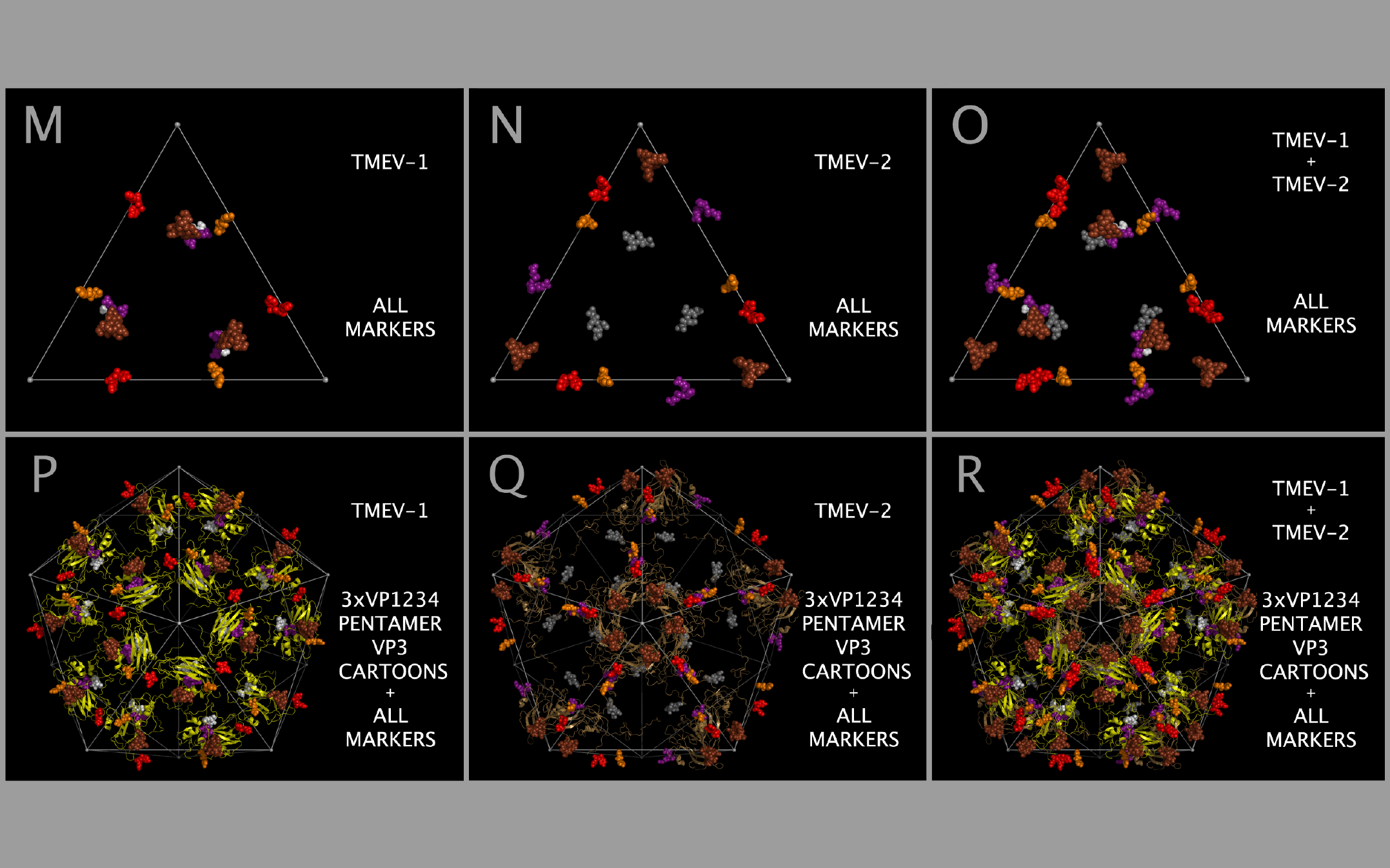
Constructing the TMEV-1 and TMEV-2 capsid tiling pieces allowed us to explore the impact of residue positional variation in the constructed capsids. While the static coordinates of the X-ray crystal structures are dependent on the crystallization conditions, including solvents and co-crystallized molecules, they are examples of possible, stable, orientations of the crystallized VP1, VP2, VP3, and VP4 protein assemblies (VP1234). Figure 12 shows, in the context of constructed capsid proteins, how corresponding residues in the X-ray crystal structures of the VP1234 for TMEV-1 and TMEV-2 are in different positions. This structural variation between the TMEV-1 VP1234 and TMEV-2 VP1234 can be interpreted as permitted relative motion of capsid parts. Figure 12 Panels A and B show the VP1 proteins in the TMEV-1 and TMEV-2 capsid tiling pieces (3xVP1234) and Panel C shows their superposition; Panels D and E show the VP2 proteins in the TMEV-1 and TMEV-2 capsid tiling pieces and Panel F shows their superposition; Panels G and H show the VP3 proteins in the TMEV-1 and TMEV-2 capsid tiling pieces and Panel I shows their superposition; and Panels J and K show VP4 proteins and a portion of VP1 (i.e., the white and grey residue marker spheres) in the TMEV-1 and TMEV-2 capsid tiling pieces and Panel L shows their superposition. The position and identity of corresponding representative residue markers in TMEV-1 and TMEV-2 in Figure 12 are noted in the Figure 1 row labelled “SUBSECTION DESCRIPTOR MARKER” with the subsection title suffix “-M.”
As can be seen in Figure 5, the sequence and spatially invariant VP3 prolines listed in Tables 3 and 4 are positioned at the yellow vertices of TRI-78. In Figure 12 Panels A — L, additional sequence equivalent residues (“markers”) from TMEV-1 and TMEV-2 are shown and can be used to track relative positional differences in the TMEV-1 and TMEV-2 constructed capsids. In Figure 12 Panels M — O, the white (TMEV-1 VP1 S11-N12-D13-D14) and grey (TMEV-2 VP1 S11-N12-D13-D14) residue marker spheres indicate the small relative difference in position of these residues on the RNA side of the constructed capsid. The white and grey residue markers of Figure 12 Panels M — O correspond to residues in the myelin P2 helix residues in Figure 1 Section M-2. The other residue markers (red, brown, orange, and purple) shown in Figure 12 Panels M — O have significantly different relative positions in the TMEV-1 and TMEV-2 capsid tiling pieces. Figure 12 Panels P and Q show the VP3 protein cartoons and the corresponding VP1, VP2, and VP3 residue marker spheres in pentamers of TMEV-1 and TMEV-2 capsid tiling pieces and Figure 12 Panel R shows their superposition. An examination of the similarities and differences in the position of these markers indicates that the VP3 proteins in the capsid appear to change position relative to one another in a way that resembles the opening and closing of an iris diaphragm shutter with the VP3 MP2/CRABP Cores acting as shutter components. The VP3 beta sheets are the shutter components lining the pore. The portion of the pore formed from the VP3 residues is set up to alternate between being a physical barrier and an opening for A-particle ejection.
Mapping of the relative positions of the VP3 atoms in the TMEV structures supports an interpretation that there may be a diaphragm shutter-like motion of VP3 proteins relative to VP1 and VP2 proteins. This motion would be sufficient to open and shut the capsid pentamer pore. Figure 13 panels A, B, and C show TMEV-1 and/or TMEV-2 structure cartoons with their proline residue main chain oxygen atoms as spheres. Panel D shows lines between sequence equivalent proline main chain atoms in TMEV-1 and TMEV-2. The lines in Panel D show that there is an unhindered trajectory to move the TMEV-1 VP3 structure into the TMEV-2 VP3 structure position in a diaphragm shutter-like motion.
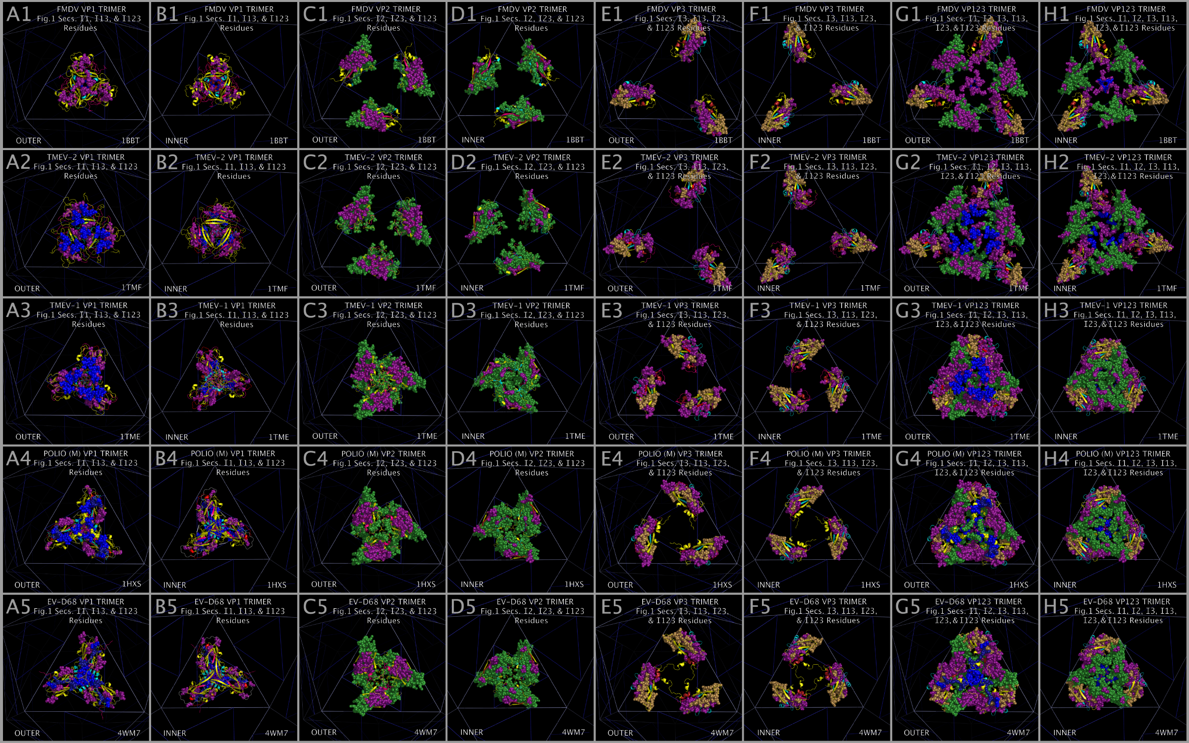
Using Insert Residue Positions To Isolate Variations in Relative Position of Aligned Structures
Figure 14 shows the FMDV, TMEV-2, TMEV-1, PV1, and EV-D68 residues that are in the Insert sections of Figure 1, i.e., the residues that are not in the Myelin P2/CRABP Core or the Toxin Core sections. Figure 14 Panels A1 — A5 and Panels B1 — B5 show Insert residues for the VP1 trimers colored according to their Figure 1 Section color. These VP1 Insert residues: appear to be concentrated on the outer face of the capsid, include residues that we have identified as possible receptor binding residues, and may impact the state of the ion channel as they are positioned over the channel at the center of the capsid face. Figure 14 Panels C1 — C5 and Panels D1 — D5 show Insert residues for the VP2 trimers colored according to their Figure 1 Section color. Figure 14 panels C and D show that VP2 Inserts are found in extended and condensed structural forms. Whether the structures are extended or condensed may directly impact the positioning of residues at the capsid face interface and therefore the state of the assembled capsid. Figure 14 Panels E1 — E5 and Panels F1 — F5 show Insert residues for the VP3 trimers colored according to their Figure 1 Section color. Figure 14 panels E and F show the VP3 Inserts are positioned to impact the functioning of the capsid pore at the vertices of the capsid faces. If the structural positional variation between TMEV-1 and TMEV-2 can be interpreted as permitted relative motion, then the positional differences in the bulk distribution of the insert residues suggest that: a) VP1 inserts take up different radial positions on the outer capsid face over a channel at the center of the tiling piece; b) VP2 inserts can twist and interlock or be separated radially relative to a channel at the center of the tiling piece; and c) VP3 inserts can pivot about conserved VP3 proline atoms. Figure 14 Panels G1 — G5 and H1 — H5 are composites of VP1, VP2, and VP3 trimer Inserts that suggest that the capsid is capable of cooperatively and reversibly undergoing an extended to condensed structural change.
Each Picornavirus Capsid Tiling Piece Has A Myelin-P2 Trimer-like Ion Channel At Its Center
Superposition of the myelin P2 trimers with the picornavirus capsid tiling pieces also reveals that each myelin trimer, CRABP trimer, and picornavirus capsid tiling piece presents an ion channel-like structure at their centers (“Ion Channel”). The Ion Channel is formed by residues in the Myelin P2/CRABP Core Figure 1 Sections M-5, M-6, M-7, M-8, M-9, M-10, M-13, and M-14 (“Channel Sections”). An examination and comparison of structures in Figure 8 indicates that the Ion Channels are gated by the residues found in Figure 1 Sections M2, M3, and M4 (“Helix Sections”). Figure 15 shows the Channel Section residues and Helix Section residues for the myelin P2 trimer and the FMDV, TMEV-2, TMEV-1, EV-D68, and PV1 VP1 trimers. Channel Section residues are shown as spheres. Helix Section residues are shown as dots. Figure 15 Panels in column one (A1, B1, C1, D1, E1, and F1) and column two (A2, B2, C2, D2, E2, and F2) show the OUTER view. Figure 15 Panels in column three (A3, B3, C3, D3, E3, and F3) and column 4 (A4, B4, C4, D4, E4, and F4) show the INNER view. As can be seen in Figure 15 Panels A1 — A4, the myelin P2 Helix Section (Figure 1 Section B) residues are positioned such that they are not in the constructed myelin P2 Ion Channel. Similarly, the VP1 Helix Section residues in EV-D68, PV1, and TMEV-1 also take up a radial position that places these residues away from the Ion Channel. In contrast, FMDV and TMEV-2 have VP1 Helix Section residues placed in or about the Ion Channel. It can be seen from Figure 15 Panels B4 and C4 that FMDV and TMEV-2 have VP1 Helix Section residues (dots) in the Ion Channel. This is in extreme contrast to the TMEV-1 Helix Section residues shown in Figure 15 Panel D4. This suggests that the Helix Section residues can be moved into a position to gate the Ion Channels in the capsid when the Ion Channel is open. The fact that TMEV-1 and TMEV-2 have nearly identical sequences and that the Helices Section residues take up different radial positions (as shown in Figure 15 Panels C4 and D4) supports the assertion that the Helix Section residues are involved in “gating” the Ion Channel.
Any interaction that locks the Ion Channel, i.e., that prevents the transition of a closed channel to an open channel or prevents the Helix Section residues from taking up a position over the Ion Channel would be expected to impact the functioning of the Ion Channel and therefore impact viral uncoating. As shown in Figure 15 Panels E1 and F1, the ability to reposition VP1 residues between channel transition states may be altered in EV-D68 and PV1 as there are no negatively charged residues in the channel area lobes to attract positively charged potassium ions. For comparison, Figure 15 Panel G1 and G2 show residues (G53 to P83) from the functionally validated Streptomyces lividans potassium ion channel [49] holding potassium ions. As can be seen from Figure 15 Panels G1 and G2, the potassium ions (white spheres) are attracted to the channel by the negatively charged residues that ring the channel. Figure 15 Panels G3 and G4 show the same potassium atoms superposed in the TMEV-2 VP1 Ion Channel with the Helix Two residues not shown. As can be seen from an examination of Figure 15 Panels G3 and G4, the potassium atoms fit well within the Ion Channel with a set of valine (VP1 VAL41) residues poised to strip the waters from the potassium atoms as they transverse the Ion Channel. The VP1 Ion Channel appears to have many of the features of a potassium channel: negative residues to attract the potassium ion to the channel, residues in the channel that can strip the waters from the potassium ion as it transverses the channel, and residues that can “pull” the potassium atoms through the channel by changing position over the channel.
Discussion
Picornavirus capsids are formed largely from Myelin P2/CRABP Cores and Toxin Cores. We showed that myelin P2 and alpha-bungarotoxin sequences are threaded in specific regions of the picornavirus VP1, VP2, and VP3 sequences, suggesting that the picornaviruses are evolutionarily related to myelin P2, CRABP, and toxins. Model myelin P2 and CRABP trimers can be formed by mapping atoms in myelin P2 and CRABP onto points used to tile the picornavirus VP1234. At the center of each picornavirus capsid face (seen in the center of the model capsid tiling piece) appears to be an ion channel gated by the MP2/CRABP-like helices. Each picornavirus capsid vertex (seen in the center of a pentamer of model capsid tiling pieces) presents a separate pore that has the features of a diaphragm shutter. An influx of ions entering through the gated ion channel may function to eject the A-particle through the pore.
EV-D68, EV-D70, and PV1 capsids present the components of TOX DOMAIN on their capsids and are associated with infection induced paralysis. This TOX DOMAIN has loops that are similar to those found on alpha-bungarotoxin, staphylococcal enterotoxin I, botulinum toxin, anthrax lethal factor, tetanus toxin, and the highly anomalous emergent influenza virus H18N11 (Table 9 (local link) of Reference [12] and Figure 12 (local link) of Reference [12]). The absence in specific picornaviruses of some of the residues in the alpha-bungarotoxin loops that are common to toxins suggests that the picornaviruses may not have had or may not have maintained all of the toxin binding components. However, we found that the complete TOX DOMAIN has been reacquired by specific emergent viruses such as EV-D68 and EV-D70. This TOX DOMAIN has previously been seen in Mahoney poliovirus PV1. A comparison of the presentation of alpha-bungarotoxin residues in alpha-bungarotoxin trimers superposed with the VP1 trimers of EV-D68 and PV1 suggests that residues from VP1 and VP2 trimers of EV-D68 and VP1 trimers of PV1 may have some capacity to engage acetylcholine receptors and that this is related to their ability to induce paralysis. We hypothesize that TOX DOMAINS found in ABT, PV1, EV-D68, and EV-D70 are the structures responsible for the binding of the capsids and the proteins toxins to the acetylcholine receptor and that this binding is the cause of paralysis. The PV1 TOX DOMAIN and pathogenic EV-D68, EV-D70, EV-D94, and HRV-87 TOX DOMAINS are comprised of residues on loops that are found in the same spatial position on the virus capsid as in the constructed alpha-bungarotoxin chain B trimer (all residues). There is no threading of alpha-bungarotoxin chain B residues 49 — 74 in VP1, instead, the loops that complete the TOX DOMAIN (“SPATIALLY RECONSTITUTED TOXIN LOOPS”) are seen in inserts and are in anomalous positions. SPATIALLY RECONSTITUTED TOXIN LOOPS are present both in Figure 1 VP1 ONLY Section I1-2 Inserts (as in the case of PV1, EV-D68, EV-D70, EV-D94, and HRV-87) and in positions in sequences not associated with the Toxin Cores (i.e., M-12, as in the case of PV1). Our findings suggest that the EV-D68, EV-D70, and PV1 virus can engage motor neurons by binding to the nicotinic acetylcholine receptor using the alpha-bungarotoxin-like residues. The presence of structures on the EV-D68 capsid necessary to engage the nicotinic acetylcholine receptor may be associated with the susceptibility, especially of young children, to limb paralysis due to EV-D68 infection. EV-D68 and EV-D70 may also be engaging cells using their ability to bind sialic acid. The ability to engage sialic acid broadens the cell entry options of the virus, broadens the cellular reservoirs of the virus, and creates a persistent threat of nervous system infection upon re-activiation of the EV-D68 or EV-D70 virus.
That injected myelin P2 and infection by TMEV can each cause a multiple sclerosis-like disease, and that myelin P2-like helices are present on picornaviruses suggests that there is a viral origin to some human multiple sclerosis due to the presentation of the myelin P2-like helices by the virus to the immune system during infection. We suggest that any chemical that induces channel dysfunction may inhibit to some extent viral infection but could result in exposure of the MP2/CRABP-like helices to the immune system during viral uncoating. Molecules that bind to the alpha-bungarotoxin-like domains of EV-D68 may have the effect of inhibiting channel function but may also induce the exposure of the MP2/CRABP-like helices in viral particles that bind the acetylcholine receptor. Any chemical that induces the exposure of the MP2/CRABP-like helices during partial uncoating of the capsid would be expected to induce multiple sclerosis. We hypothesize that the binding of EV-D68/EV-D70 alpha-bungarotoxin components to acetylcholine receptors is the cause of Acute Flaccid Paralysis by EV-D68 and EV-D70, and that this binding produces incomplete capsids that expose the myelin P2/CRABP helices in the capsid tiling piece initiating multiple sclerosis. We hypothesize that it is the binding of the acetylcholine receptor and initiation of multiple sclerosis that results in episodic Guillain-Barré Syndrome.
The center of each picornavirus capsid face (seen in the center of the model capsid tiling piece) appears to be an ion channel gated by the MP2/CRABP-like helices. The fact that the constructed myelin P2 and CRABP trimers have internal channels lined with charged residues and that the same channel surfaces are presented in TMEV-2 argues that both myelin P2 trimers and picornavirus capsid tiling pieces may have ion channels. The fact that EV-D68-4WM7 does not have a balance of charge in the same structures that would form the channel in other picornaviruses suggests that EV-D68-4WM7 employs a different mechanism utilizing alpha-bungarotoxin-like or sialidase-like domains to enter cells. Each picornavirus capsid vertex (seen in the center of a pentamer of model capsid tiling pieces) presents a separate pore that has the features of a diaphragm shutter. An influx of ions entering through the gated ion channel may function to eject the A-particle through the pore.
Conserved proline atoms in the VP1, VP2, and VP3, when mapped onto the faces of an icosahedron, allow the construction of a complete model capsid for each picornavirus. The superposition of model picornavirus VP1-VP2-VP3-VP4 assemblies (“VP1234”) onto an idealized structure using VP1, VP2, and VP3 atoms that are internal to the VP1234 assembly shows that the tiling of the virus capsid and the overall capsid structure is inherent to the VP1-VP2-VP3 assembly structure. All picornavirus model structures thus created share a common reference frame making it possible to perform a comparative structural analysis. The use of atoms with conserved geometry to superpose structures [12] is also a powerful tool and is essential for the comparative structural anatomy of molecules. The ability to identify and relate the structural and functional correlates of sequence variation in emergent viruses from previously unrelated molecules is especially critical in evaluating emerging pathogens and in identifying new features on emergent viruses. Alignment of sequences to reference sequences provides a means of isolating and relating common structural features in previously unassociated proteins. We have demonstrated the usefulness of using reference sequences, prolines and glycines, and unique residue groupings to bracket and align groups of residues. The previously unassociated proteins myelin P2, CRABP, and alpha-bungarotoxin were used to organize and parse the structures of the picornavirus VP1, VP2, and VP3 proteins. The use of reference structures, such as myelin P2, CRABP, and alpha-bungarotoxin, to define structural groupings within a functionally divergent class of proteins, such as the picornavirus VP1, VP2, and VP3 proteins, is a powerful, general tool. The identification of myelin P2-like, CRABP-like, and alpha-bungarotoxin-like sequences threaded through the picornavirus VP1, VP2, and VP3 proteins illustrate the method of using reference sequences to align structural groups and isolate functional groups.
Supporting Information
ICOS135.PDB
Ideal 135 Angstrom-on-an-edge icosahedron (“ICOS135”).
TRI78.PDB
Ideal 78 Angstrom-on-a-side equilateral triangles (“TRI78”), positioned with their vertices on ICOS135 icosahedron edges, and 45 (and 90) Angstroms away from ICOS135 icosahedron vertices.
CASOG_ONE_CAPSID_POINTS.PDB
Points at the vertices of scalene equilateral triangles coplanar with, positioned within, and sharing one vertex with, TRI78 triangles.
CASOG_TWO_CAPSID_POINTS.PDB
Ideal 26 Angstrom-on-a-side equilateral triangles (“TRI26”), positioned at the corner of, and coplanar with, TRI78 equilateral triangles.
PICORNAVIRUS_TILING_POINTS.PDB
Idealized superposition points (“PICORNAVIRUS TILING POINTS”) for creating picornavirus capsid tiling pieces, myelin P2 trimers, and CRABP trimers. PICORNAVIRUS TILING POINTS are all located on or within the first listed triangle in TRI78, which is within the first ICOS135 listed triangle (i.e., the first icosahedron face). Chain 1 contains CASOG-1 tiling points. Chain 2 contains CASOG-2 tiling points. Chain 3 contains myelin P2/CRABP trimer tiling points.
References
1. Greninger AL, Naccache SN, Messacar K, Clayton A, Yu G, Somasekar S, Federman S, Stryke D, Anderson C, Yagi S, Messenger S, Wadford D, Xia D, Watt JP, Van Haren K, Dominguez SR, Glaser C, Aldrovandi G, Chiu CY. (2015) A novel outbreak enterovirus D68 strain associated with acute flaccid myelitis cases in the USA (2012—2014): a retrospective cohort study. Lancet Infect Dis. June 15(6):671-82. doi: 10.1016/S1473-3099(15)70093-9
2. Williams C, Thomas R, Pickersgill T, Lyons M, Lowe G, Stiff R, Moore C, Jones R, Howe R, Brunt H, Ashman A, Mason B. (2016) Cluster of atypical adult Guillain-Barré syndrome temporally associated with neurological illness due to EV-D68 in children, South Wales, United Kingdom, October 2015 to January 2016. Euro Surveill. 21(4):pii=30119. doi: 10.2807/1560-7917.ES.2016.21.4.30119
3. Dal Canto MC, Lipton HL. (1977) Multiple sclerosis. Animal model: Theiler's virus infection in mice. Am J Pathol 88:497—500 PMID:195474. Available: http://www.ncbi.nlm.nih.gov/pmc/articles/PMC2032181/
4. Kadlubowski,M. and Hughes,R.A.C. (1979) Identification of the neuritogen for experimental allergic neuritis. Nature, 277, 140—142. doi: 10.1038/277140a0
5. Protein Data Bank ID: 1CBS Kleywegt GJ, Bergfors T, Senn H, Le Motte P, Gsell B, Shudo K, Jones TA. (1994) Crystal structures of cellular retinoic acid binding proteins I and II in complex with all-trans-retinoic acid and a synthetic retinoid. Structure 2(12):1241—1258. doi: 10.1016/s.0969-2126(94)00125-1
6. Protein Data Bank ID: 2WUT Majava V, Polverini E, Mazzini A, Nanekar R, Knoll W, Peters J, Natali F, Baumgartel P, Kursula I, Kursula P. (2010) Structural and functional characterization of human peripheral nervous system myelin protein p2. Plos One 5:E300-d10300. doi: 10.1371/journal.pone.0010300
7. Protein Data Bank ID: 2ABX Love RA, Stroud RM. (1986) The crystal structure of alpha-bungarotoxin at 2.5 A resolution: relation to solution structure and binding to acetylcholine receptor. Protein Eng. 1(1):37—46. doi: 10.1093/protein/1.1.37
8. Protein Data Bank ID: 1HXS Miller ST, Hogle JM, Filman DJ. (2001) Ab initio phasing of high-symmetry macromolecular complexes: successful phasing of authentic poliovirus data to 3.0 A resolution. J.Mol.Biol. 307:499—512. doi: 10.1006/jmbi.2001.4485
9. Protein Data Bank ID: 1EAH Lentz KN, Smith AD, Geisler SC, Cox S, Buontempo P, Skelton A, Demartino J, Rozhon E, Schwartz J, Girijavallabhan V, O'Connell J, Arnold E. (1997) Structure of poliovirus type 2 Lansing complexed with antiviral agent SCH48973: comparison of the structural and biological properties of three poliovirus serotypes. Structure. 5:961—978. doi: 10.1016/s0969-2126(97)00249-9
10. Protein Data Bank ID: 1PIV Hiremath CN, Grant RA, Filman DJ, Hogle DJ. (1995) Binding of the antiviral drug WIN51711 to the Sabin strain of type 3 poliovirus: structural comparison with drug binding in rhinovirus 14. Acta Crystallogr.,Sect.D. 51:473—489. doi: 10.1107/s090744499401084x
11. Protein Data Bank ID: 4WM7 Liu Y, Sheng J, Fokine A, Meng G, Long F, Kuhn RJ, Rossmann MG. (2014) Virus structure. Structure and inhibition of EV-D68, a virus that causes respiratory illness in children. Science 347(6217):71—74. doi: 10.1126/science.1261962
12. Weininger A, Weininger S. (2015) Using Common Spatial Distributions of Atoms to Relate Functionally Divergent Influenza Virus N10 and N11 Protein Structures to Functionally Characterized Neuraminidase Structures, Toxin Cell Entry Domains, and Non-influenza Virus Cell Entry Domains. PLoS One 10(2):e0117499. doi: 10.1371/journal.pone.0117499
13. Protein Data Bank ID: 1W1X Rudino-Pinera E, Tunnah P, Crennell SJ, Webster RG, Laver WG, Garman EF. (2004)
14. Protein Data Bank ID: 1BBT Fry E, Acharya R, Stuart D. (1993) Methods used in the structure determination of foot-and-mouth disease virus. Acta Crystallogr.,Sect.A. 49:45—55. doi: 10.1107/s0108767392005737
15. Fricks CE, Hogle JM. (1990) Cell-induced conformational change in poliovirus: externalization of the amino terminus of VP1 is responsible for liposome binding. J. Virol. 64:1934—1945.
16. De Sena J, Mandel B. (1977) Studies on the in vitro uncoating of poliovirus II. Characteristics of the membrane–modified particle. Virology. 78:554—566.
17. Brandenburg B, Lee LY, Lakadamyali M, Rust MJ, Zhuang X, Hogle JM. (2007) Imaging poliovirus entry in live cells. PLoS Biol. 5:1543-1555. doi: 10.1371/journal.pbio.0050183
18. Ren J, Wang X, Hu Z, Gao Q, Sun Y, Li X, Porta C, Walter TS, Gilbert RJ, Zhao Y, Axford D, Williams M, McAuley K, Rowlands DJ, Yin W, Wang J, Stuart DI, Rao Z, Fry EE. (2013) Picornavirus uncoating intermediate captured in atomic detail. Nat. Commun. 4:1929. doi: 10.1038/ncomms2889
19. Protein Data Bank ID: 1TME Grant RA, Filman DJ, Fujinami RS, Icenogle JP, Hogle JM. (1992) Three-Dimensional Structure Of Theiler's Virus. Proc. Natl. Acad. Sci. USA. 89:2061—2065. doi: 10.1073/pnas.89.6.2061
20. Protein Data Bank ID: 1TMF Luo M, He C, Toth KS, Zhang CX, Lipton HL. (1992) Three-Dimensional Structure Of Theiler's Murine Encephalomyelitis Virus (Bean Strain). Proc. Natl. Acad. Sci. USA. 89:2409—2413. doi: 10.1073/pnas.89.6.2409
21. Protein Data Bank ID: 3VBH Wang X, Peng W, Ren J, Hu Z, Xu J, Lou Z, Li X, Yin W, Shen X, Porta C, Walter TS, Evans G, Axford D, Owen R, Rowlands DJ, Wang J, Stuart DI, Fry EE, Rao Z. (2012) A sensor-adaptor mechanism for enterovirus uncoating from structures of EV71. Nat.Struct.Mol.Biol. 19:424—429. doi: 10.1038/nsmb.2255
22. Protein Data Bank ID: 4CEW De Colibus L, Wang X, Spyrou JAB, Kelly J, Ren J, Grimes J, Puerstinger G, Stonehouse N, Walter TS, Hu Z, Wang J, Li X, Peng W, Rowlands DJ, Fry EE, Rao Z, Stuart DI. (2014) More-powerful virus inhibitors from structure-based analysis of HEV71 capsid-binding molecules. Nat. Struct. Mol. Biol. 21:282—288. doi: 10.1038/nsmb.2769
23. Protein Data Bank ID: 1D4M Hendry E, Hatanaka H, Fry E, Smyth M, Tate J, Stanway G, Santti J, Maaronen M, Hyypia T, Stuart D. (1999) The crystal structure of coxsackievirus A9: new insights into the uncoating mechanisms of enteroviruses. Structure Fold. Des. 7:1527—1538. doi: 10.1016/s0969-2126(00)88343-4
24. Protein Data Bank ID: 1JEW He Y, Chipman PR, Howitt J, Bator CM, Whitt MA, Baker TS, Kuhn RJ, Anderson CW, Freimuth P, Rossmann MG. (2001) Interaction of Coxsackievirus B3 with the full length Coxsackievirus-Adenovirus receptor. Nat. Struct. Biol. 8:874—878. doi: 10.1038/nsb1001-874
25. Protein Data Bank ID: 1M11 He Y, Lin F, Chipman PR, Bator CM, Baker TS, Shoham M, Kuhn RJ, Medof ME, Rossmann MG. (2002) Structure of decay-accelerating factor bound to echovirus 7: a virus-receptor complex. Proc. Natl. Acad. Sci. USA. 99:10325—10329. doi: 10.1073/pnas.152161599
26. Protein Data Bank ID: 1OOP Fry EE, Knowles NJ, Newman JWI, Wilsden G, Rao Z, King AMQ, Stuart DI. (2003) Crystal Structure of Swine Vesicular Disease Virus and Implications for Host Adaptation. J. Virol. 77:5475—5486. doi: 10.1128/jvi.77.9.5475-5486.2003
27. Protein Data Bank ID: 1Z7S Xiao C, Bator-Kelly CM, Rieder E, Chipman PR, Craig A, Kuhn RJ, Wimmer E, Rossmann MG. (2005) The crystal structure of Coxsackievirus A21 and its interaction with ICAM-1. Structure 13:1019—1033. doi: 10.1016/j.str.2005.04.011
28. Protein Data Bank ID: 4Q4Y Zocher G, Mistry N, Frank M, Hahnlein-Schick I, Ekstrom JO, Arnberg N, Stehle T. (2014) A sialic acid binding site in a human picornavirus. Plos Pathog. 10:e1004401. doi: 10.1371/journal.ppat.1004401
29. Protein Data Bank ID: 1BEV Smyth M, Tate J, Hoey E, Lyons C, Martin S, Stuart D. (1995) Implications for viral uncoating from the structure of bovine enterovirus. Nat. Struct. Biol. 2:224—231. doi: 10.1038/nsb0395-224
30. Protein Data Bank ID: 1V9U Verdaguer N, Fita I, Reithmayer M, Moser R, Blaas D. (2004) X-ray structure of a minor group human rhinovirus bound to a fragment of its cellular receptor protein Nat.Struct.Mol.Biol. 11:429—434. doi: 10.1038/nsmb753
31. Protein Data Bank ID: 1AYM Hadfield AT, Lee W, Zhao R, Oliveira MA, Minor I, Rueckert RR, Rossmann MG. (1997) The refined structure of human rhinovirus 16 at 2.15 A resolution: implications for the viral life cycle. Structure. 5:427—441. doi: 10.1016/s0969-2126(97)00199-8
32. Protein Data Bank ID: 1D3I Kolatkar PR, Bella J, Olson NH, Bator CM, Baker TS, Rossmann MG. (1999) Structural studies of two rhinovirus serotypes complexed with fragments of their cellular receptor. EMBO J. 18:6249—6259. doi: 10.1093/emboj/18.22.6249
33. GenBank: AAO84300.1 Coxsackievirus B1, polyprotein. Tam PE, Weber-Sanders ML, Messner RP. (2003) Multiple Viral Determinants Mediate Myopathogenicity in Coxsackievirus B1-Induced Chronic Inflammatory Myopathy. Direct Submission. Medicine/Division of Rheumatic and Autoimmune Diseases, Minnesota, 420 Delaware St. SE,MMC 108, Minneapolis, MN 55455, USA. J.Virol. 77(21):11849—11854. doi: 10.1128/jvi.77.21.11849-11854.2003
34. GenBank: AET37232.1 Coxsackievirus B1, polyprotein. Bachtler M, Frey BM, Frey FJ, Gorgievski, M, Simonetti G, Pasch A. (2011) Direct Submission. Department of Nephrology & Hypertension, University of Bern, Freiburgstrasse 15, Bern, BE 3010, Switzerland.
35. NCBI Reference Sequence: NP_040958 Coxsackievirus B1, polyprotein. Iizuka N, Kuge S, Nomoto A. (1987) Direct Submission. National Center for Biotechnology Information, NIH, Bethesda, MD 20894, USA. Complete nucleotide sequence of the genome of coxsackievirus B1. Virology. 156(1):64—73. doi: 10.1016/0042-6822(87)90436-3
36. UniProtKB/Swiss-Prot: P03313.4 Coxsackievirus B3 (strain Nancy), genome polyprotein.
37. GenBank: AAF12719.1 Coxsackievirus B6, polyprotein. Martino TA, Tellier R, Petric M, Irwin DM, Afshar A, Liu PP. (1999) The complete consensus of coxsackievirus B6 and generation of infectious clones by long RT-PCR. Direct Submission. Center for Cardiocascular Research, Toronto Hospital, 200 Elizabeth Street, EC12-324, Toronto, Ontario M5G 2C4, Canada. Virus. Res. 64(1):77—86. doi: 10.1016/S0168-1702(99)00081-7
38. GenBank: JX514943.1 Enterovirus C105, polyprotein. Lukashev AN, Drexler JF, Kotova VO, Amjaga EN, Reznik VI, Gmyl AP, Grard G, Tay Taty R, Trotsenko O E , Leroy EM, Drosten C. (2012) Direct Submission. Chumakov Institute of Poliomyelitis and Viral Encephalitides, Moscow 142782, Russia. Novel types 105 and 116 are members of distinct subgroups of Human enterovirus C. J Gen Virol. 93(Pt 11):2357—2362. doi: 10.1099/vir.0.043216-0
39. GenBank: AIZ48771.1 Enterovirus D68, polyprotein. Zhang T. (2014) Direct Submission. Beijing Center for Disease Prevention and Control, Institute of Immunization and Prevention, 16, Hepingli Middle Avenue of Dongcheng District, Beijing, Beijing 100013, China.
40. GenBank: BAK08580.1 Enterovirus D68, polyprotein. Kaida A, Kubo H, Sekiguchi J, Kohdera U, Togawa M, Shiomi M, Nishigaki T, Iritani N. (2011) Direct Submission. Osaka City Institute of Public Health and Environmental Sciences, Microbiology; 8-34, Tojo-cho, Tennoji-ku, Osaka, Osaka 5430026, Japan. Enterovirus 68 in children with acute respiratory tract infections, Osaka, Japan. Emerg Infect Dis. 17:1494—1497. doi: 10.3201/eid1708.110028
41. GenBank: AGC00381.1 Enterovirus D68, polyprotein. Todd AK, Hall RJ, Wang J, Peacey M, McTavish S, Rand CJ, Stanton JA, Taylor S, Huang QS. (2013) Direct Submission. National Centre for Biosecurity and Infectious Disease, Institute of Environmental Science and Research Limited, 66 Ward Street, Wallaceville, Upper Hutt, Wellington 5018, New Zealand. Detection and whole genome sequence analysis of an enterovirus 68 cluster. Virol. J. 10:103. doi: 10.1186/1743-422x-10-103
42. GenBank: ABL61317.1 Enterovirus D68, polyprotein. Smura TP, Junttila N, Blomqvist S, Norder H, Kaijalainen S, Paananen A, Magnius LO, Hovi T, Roivainen M. (2007) Direct Submission. Department Viral Diseases and for Virology, Immunology, and Vaccinology. Swedish Institute for Infectious Disease Control, Vhe, Solna SE-171 82, Sweden. Enterovirus 94, a proposed new serotype in human enterovirus species D. J Gen Virol. 88(Pt 3):849—858. doi: 10.1099/vir.0.82510-0
43. GenBank: AIS73051.1 Enterovirus D68, polyprotein. Brown BA, Nix WA, Sheth M, Frace M, Oberste MS. (2014) Direct Submission. Polio and Picornavirus Laboratory Branch, Centers for Disease Control and Prevention, 1600 Clifton Road, NE Atlanta, GA 30333, USA. Seven Strains of Enterovirus D68 Detected in the United States during the 2014 Severe Respiratory Disease Outbreak. Genome Announc. 2(6):e01201—14. doi: 10.1128/genomea.01201-14
44. GenBank: AIS73057.1 Enterovirus D68, polyprotein. Brown BA, Nix WA, Sheth M, Frace M, Oberste MS. (2014) Direct Submission. Polio and Picornavirus Laboratory Branch, Centers for Disease Control and Prevention, 1600 Clifton Road, NE Atlanta, GA 30333, USA. Seven Strains of Enterovirus D68 Detected in the United States during the 2014 Severe Respiratory Disease Outbreak. Genome Announc. 2(6):e01201—14. doi: 10.1128/genomea.01201-14
45. GenBank: BAA18891.1 Human enterovirus 70, polyprotein. Ryan MD, Jenkins O, Hughes PJ, Brown A, Knowles NJ, Booth D, Minor PD, Almond JW. (1990) The complete nucleotide sequence of enterovirus type 70: relationships with other members of the picornaviridae. J. Virol. 71:2291—2299. doi: 10.1099/0022-1317-71-10-2291
46. GenBank: ABK88241.1 Human enterovirus 94, polyprotein. Smura TP, Junttila N, Blomqvist S, Norder H, Kaijalainen S, Paananen A, Magnius LO, Hovi T, Roivainen M. (2007) Direct Submission. Department of Viral Diseases and Immunology, National Public Health Institute, Mannerheimintie 166, Helsinki 00300, Finland. Enterovirus 94, a proposed new serotype in human enterovirus species D. J Gen Virol. 88(Pt 3):849—858. doi: 10.1099/vir.0.82510-0
47. GenBank: AAQ19942.1 Human rhinovirus 87, VP1 capsid protein, partial. Ledford RM, Patel NR, Demenczuk TM, Watanyar A, Herbertz T, Collett MS, Pevear DC. (2004) Direct Submission. Viropharma, Inc, 405 Eagleview Blvd, Exton, PA 19341, USA. J.Virol. 78:3663—3674. doi: 10.1128/jvi.78.7.3663-3674.2004
48. GenBank: AAK85711.1 Echovirus E7, VP1 polyprotein. Chua KB, Chua BH, McMinn PC, Lam SK, Smith DW (2001) Direct Submission. Medical Microbiology, University Malaya Medical Centre, Faculty of Medicine, Kuala Lumpur, FT 50603, Malaysia. Comparison of the complete nucleotide sequences of echovirus 7 strain UMMC and the prototype (Wallace) Strain demonstrates significant genetic drift over time. J. Gen Virol. 82:2629—1639. doi: 10.1099/0022-1317-82-11-2629
49. Protein Data Bank ID: 1BL8 Potassium channel (KCSA) from streptomyces lividans. (1998) Doyle DA, Morais Cabral J, Pfuetzner RA, Kuo A, Gulbis, JM, Cohen SL, Chait BT, Mackinnon R. (1998) The structure of the potassium channel: molecular basis of K+ conduction and selectivity. Science 280:69. doi: 10.1126/science.280.5360.69
Tables
Table 1. Abbreviations, reference numbers, sequence and structure sources, description and structure resolutions.
| Abbreviation | Ref. | Source | Description | Resolution |
| ABT | 7 | 2ABX.pdb | Alpha-bungarotoxin | 2.50° |
| CRABP | 5 | 1CBS.pdb | CRABP I and II w/ all-trans-retinoic acid and a retinoid | 1.80° |
| EVA-71-1 | 21 | 3VBH.pdb | Enterovirus 71 (FUYANG, ANHUI. P.R.C/17.08/1) | 2.30° |
| EVA-71-2 | 22 | 4CEW.pdb | Human Enterovirus 71 with Uncoating Inhibitor ALD | 2.75° |
| EV-B5-SVDV | 26 | 1OOP.pdb | Swine Vesicular Disease Virus | 3.00° |
| EV-B-CV-A9 | 23 | 1D4M.pdb | Coxsackievirus A9 | 2.90° |
| EV-B-CV-B1 | 33 | AAO84300 | Coxsackievirus B1 | |
| EV-B-CV-B1 | 34 | AET37232 | Coxsackievirus B1 | |
| EV-B-CV-B1 | 35 | NP_040958 | Coxsackievirus B1 | |
| EV-B-CV-B3 | 36 | P03313 | Coxsackievirus B3 (strain Nancy) | |
| EV-B-CV-B3M | 24 | 1JEW.pdb | Coxsackievirus B3 (M Strain) w/cellular receptor (CAR) | 22.00° |
| EV-B-CV-B6 | 37 | AAF12719 | Coxsackievirus B6 | |
| EV-B-ECHOV-7 | 25 | 1M11.pdb | Echovirus 7 w/bound Human Decay-Accelerating Factor | 16.00° |
| EV-B-ECHOV-7+ | 45 | AAK85711 | Echovirus E7 | |
| EV-C-CV-A21 | 27 | 1Z7S.pdb | Coxsackievirus A21 | 3.20° |
| EV-C-CV-A24 | 28 | 4Q4Y.pdb | Coxsackievirus A24V w/Disialyllacto-N-Tetraose(DSLNT) | 1.88° |
| EV-C-CV-C105 | 38 | JX514943 | Human Enterovirus C105 | |
| EV-C-PV1-M | 8 | 1HXS.pdb | Poliovirus Type 1 (Mahoney) | 2.20° |
| EV-C-PV2 | 9 | 1EAH.pdb | Poliovirus Type 2 (Lansing) with antiviral (SCH48973) | 2.90° |
| EV-C-PV3-S | 10 | 1PIV.pdb | Poliovirus Type 3 (P3/LEON) with antiviral (WIN51711) | 2.90° |
| EV-D68-CH14 | 39 | AIZ48771 | Enterovirus D68 | |
| EV-D68-JP11 | 40 | BAK08580 | Enterovirus D68 | |
| EV-D68-NZ13 | 41 | AGC00381 | Enterovirus D68 | |
| EV-D68-SW07 | 42 | ABL61317 | Enterovirus D68 | |
| EV-D68-4WM7 | 11 | 4WM7.pdb | Enterovirus D68 complexed with PLECONARIL | 2.32° |
| EV-D68-US14-1 | 43 | AIS73051 | Enterovirus D68 | |
| EV-D68-US14-2 | 44 | AIS73057 | Enterovirus D68 | |
| EV-D-HRV87-US4 | 47 | AAQ19942 | VP1 capsid protein, partial [BHuman rhinovirus 87] | |
| EV-D70-UK09 | 45 | BAA18891 | Enterovirus 70 | |
| EV-D94-FN07 | 46 | ABK88241 | Enterovirus 94 | |
| EV-G5-27 | 29 | 1BEV.pdb | Bovine Enterovirus VG-5-27 | 3.00° |
| FMDV | 14 | 1BBT.pdb | Foot-And-Mouth Disease Virus (BFS, 1860) | 2.60° |
| HRV-A16 | 31 | 1AYM.pdb | Rhinovirus 16 | 2.15° |
| HRV-A2 | 30 | 1V9U.pdb | Rhinovirus 2 with cellular receptor (VLDL receptor) | 3.60° |
| HRV-B14 | 32 | 1D3I.pdb | Rhinovirus 14 with cellular receptor (D1D2-ICAM-1) | 26.00° |
| MYELIN P2, MP2 | 6 | 2WUT.pdb | Human myelin protein P2 in complex with palmitate | 1.85° |
| N6 NEURAMINIDASE | 13 | 1WIX.pdb | N6 neuraminidase with sialic acid (NANA, NEU5AC) | 2.00° |
| TMEV-1 | 19 | 1TME.pdb | Theiler's murine encephalomyelitis virus | 2.80° |
| TMEV-2 | 20 | 1TMF.pdb | Theiler's murine encephalomyelitis virus (BeAn strain) | 3.50° |
Table 2. Spatially conserved atoms internal to the VP1 proteins of a representative set of picornaviruses.
| VP1 + VP2 + VP3 Internal | ||||||||||
| VP1-RES1 | VP1-RES2 | VP1-RES3 | ||||||||
| PDB | Protein | Res. | Atom | Res. | Atom | Res. | Atom | |||
| 1AYM | HRV-A16 | P | 146 | 1162 | P | 182 | 1449 | P | 248 | 2047 |
| 1BBT | FMDV | P | 90 | 703 | P | 118 | 912 | P | 188 | 1293 |
| 1BEV | EV-G5-27 | P | 147 | 1024 | P | 183 | 1287 | P | 248 | 1827 |
| 1D4M | EV-B-CV-A9 | P | 148 | 1170 | P | 184 | 1443 | P | 250 | 1984 |
| 1EAH | EV-C-PV2 | P | 161 | 1046 | P | 197 | 1325 | P | 271 | 1897 |
| 1HXS | EV-C-PV1-M | P | 161 | 1141 | P | 197 | 1425 | P | 271 | 2006 |
| 1OOP | EV-B5-SVDV | P | 147 | 1072 | P | 183 | 1343 | P | 249 | 1871 |
| 1PIV | EV-C-PV3-S | P | 161 | 1127 | P | 197 | 1406 | P | 272 | 2000 |
| 1TME | TMEV-1 | P | 147 | 1147 | P | 188 | 1450 | P | 246 | 1912 |
| 1TMF | TMEV-2 | P | 149 | 1164 | P | 190 | 1465 | P | 248 | 1927 |
| 1V9U | HRV-A2 | P | 147 | 1047 | P | 183 | 1332 | P | 247 | 1857 |
| 1Z7S | EV-C-CV-A21 | P | 156 | 1107 | P | 192 | 1393 | P | 266 | 1980 |
| 3VBH | EVA-71-1 | P | 157 | 1188 | P | 193 | 1454 | P | 263 | 2032 |
| 4CEW | EVA-71-2 | P | 157 | 1188 | P | 193 | 1454 | P | 263 | 2030 |
| 4Q4Y | EV-C-CV-A24 | P | 163 | 1114 | P | 199 | 1396 | P | 273 | 1993 |
| 4WM7 | EV-D68-4WM7 | P | 149 | 1079 | P | 185 | 1357 | P | 251 | 1850 |
Table 2 lists specific proline main chain oxygens in the VP1 proteins of a representative set of picornavirus VP1-VP2-VP3-VP4 structure assemblies (“VP1234”). For each structure, these atoms were superposed onto the listed 1BBT atoms. (1BBT was arbitrarily selected as a spatial reference frame.) The aligned picornavirus VP1234 structures are shown in Figure 4, Column 1. Proline residues listed are indicated by an “&” in the VP1 header in Figure 1 between sections: M-11 and I13-2; M14 Subsection 8 and Subsection 9; and A-1 Subsection 3 and Subsection 4.
Table 3. Common Spatial Occupancy Group One (CASOG-1) tiling atoms.
| VP1 + VP2 + VP3 External | |||||||||||
| VP1-PRO1 | VP2-PRO1 | VP3-PRO1 | |||||||||
| PDB | Protein | Orientation | Res. | Atom | Res. | Atom | Res. | Atom | |||
| 1AYM | HRV-A16 | CASOG ONE | P | 146 | 1162 | P | 128 | 3305 | P | 135 | 5375 |
| 1BEV | EV-G5-27 | CASOG ONE | P | 147 | 1024 | P | 128 | 3048 | P | 135 | 5009 |
| 1D4M | EV-B-CV-A9 | CASOG ONE | P | 148 | 1170 | P | 128 | 3207 | P | 136 | 5266 |
| 1EAH | EV-C-PV2 | CASOG ONE | P | 161 | 1046 | P | 128 | 3077 | P | 136 | 5220 |
| 1HXS | EV-C-PV1-M | CASOG ONE | P | 161 | 1141 | P | 128 | 3227 | P | 136 | 5376 |
| 1OOP | EV-B5-SVDV | CASOG ONE | P | 147 | 1072 | P | 128 | 3081 | P | 136 | 5106 |
| 1PIV | EV-C-PV3-S | CASOG ONE | P | 161 | 1127 | P | 128 | 3223 | P | 136 | 5378 |
| 1TME | TMEV-1 | CASOG ONE | P | 147 | 1147 | P | 132 | 2920 | P | 131 | 4997 |
| 1V9U | HRV-A2 | CASOG ONE | P | 147 | 1047 | P | 128 | 3077 | P | 135 | 5161 |
| 1Z7S | EV-C-CV-A21 | CASOG ONE | P | 156 | 1107 | P | 128 | 3204 | P | 135 | 5338 |
| 3VBH | EVA-71-1 | CASOG ONE | P | 157 | 1188 | P | 128 | 3240 | P | 137 | 5243 |
| 4CEW | EVA-71-2 | CASOG ONE | P | 157 | 1188 | P | 128 | 3238 | P | 137 | 5241 |
| 4Q4Y | EV-C-CV-A24 | CASOG ONE | P | 163 | 1114 | P | 128 | 3222 | P | 135 | 5372 |
| 4WM7 | EV-D68-4WM7 | CASOG ONE | P | 149 | 1079 | P | 128 | 3154 | P | 135 | 5123 |
Table 3 lists specific proline main chain oxygens in the VP1, VP2, and VP3 proteins of CASOG-1 VP1234 crystal structures. These atoms were superposed onto consecutive PICORNAVIRUS TILING POINTS having a chain identifier of “1” (i.e., the VP1-PRO1, VP2-PRO1, and VP3-PRO1 atoms were first superposed onto PICORNAVIRUS TILING POINTS 1, 2, 3, then onto 4, 5, 6, and lastly onto 7, 8, 9). The residues containing the Table 3 proline atoms are aligned in Figure 1 Sections F-1 and D-14. Figure 3 illustrates the three separate superpositions of VP1234 required to construct a CASOG-1 picornavirus capsid tiling piece (3xVP1234). The constructed CASOG-1 picornavirus capsid tiling pieces are shown in Figure 4. Proline residues listed are flanked by an “*” in Figure 1.
Table 4. Common Spatial Occupancy Group Two (CASOG-2) tiling atoms.
| VP1 + VP2 + VP3 External | |||||||||||
| VP1-PRO1 | VP2-PRO1 | VP3-PRO1 | |||||||||
| PDB | Protein | Orientation | Res. | Atom | Res. | Atom | Res. | Atom | |||
| 1BBT | FMDV | CASOG TWO | P | 90 | 703 | P | 127 | 2375 | P | 127 | 4083 |
| 1TMF | TMEV-2 | CASOG TWO | P | 149 | 1164 | P | 132 | 3160 | P | 131 | 5234 |
Table 4 lists specific proline main chain oxygens in the VP1, VP2, and VP3 proteins of CASOG-2 VP1234 crystal structures. These atoms were superposed onto consecutive PICORNAVIRUS TILING POINTS having a chain identifier of “2” (i.e., the VP1-PRO1, VP2-PRO1, and VP3-PRO1 atoms were first superposed onto PICORNAVIRUS TILING POINTS 11, 12, 13, then onto 14, 15, 16, and lastly onto 17, 18, 19). The residues containing the Table 4 proline atoms are aligned in Figure 1 Sections F-1 and D-14. Figure 3 illustrates the three separate superpositions of VP1234 required to construct a CASOG-2 picornavirus capsid tiling piece (3xVP1234). The constructed CASOG-2 picornavirus capsid tiling pieces are shown in Figure 4. Proline residues listed are flanked by an “*” in Figure 1.
Table 5. Myelin P2 trimer and CRABP trimer tiling atoms.
| Point # | Source | Atom # | Atom Type | Residue | Chain | Figure 1 Section/Subsection | |
| 1 | 2WUT | 877 | C | K | 105 | A | M-14/1 |
| 1 | 1CBS | 871 | C | T | 110 | A | M-13/3 |
| 2 | 2WUT | 330 | CG2 | I | 41 | A | M-5/2 |
| 2 | 1CBS | 324 | CD | E | 42 | A | M-5/1 |
| 3 | 2WUT | 506 | CG2 | I | 62 | A | M-6/3 |
| 3 | 1CBS | 495 | CG2 | I | 63 | A | M-6/3 |
Table 5 lists the three myelin P2 (2WUT) atoms and the three CRABP (1CBS) atoms that were separately used to construct trimers from three superpositions of individual monomers and their Figure 1 Section/Subsections. These atoms were superposed onto consecutive PICORNAVIRUS TILING POINTS having a chain identifier of “3” (i.e., points 1, 2, and 3 of 2WUT atoms, or separately of 1CBS atoms, were first superposed onto PICORNAVIRUS TILING POINTS 21, 22, 23, then onto 24, 25, 26, and lastly onto 27, 28, 29). The destination points are derived from TMEV-1 and TMEV-2 capsid tiling points. The iterative superpositions of the Table 5 atoms onto the PICORNAVIRUS TILING POINTS are illustrated in Figure 7 panels A and B. The resultant myelin P2 trimers are shown in Figure 7 panels C and D. The resultant CRABP trimers are shown with the myelin P2 trimers in Figure 7 panel D.
Table 6. Alpha-bungarotoxin and EV-D68 VP1 trimer tiling atoms.
| Point # | Source | Atom # | Atom Type | Residue | Chain | |
| 1 | 2ABX | 91 | CA | V | 14 | A |
| 1 | 4WM7 | 1412 | CB | A | 192 | A |
| 2 | 2ABX | 94 | CB | V | 14 | A |
| 2 | 4WM7 | 1415 | C | Y | 193 | A |
| 3 | 2ABX | 69 | O | P | 10 | A |
| 3 | 4WM7 | 1355 | CA | P | 185 | A |
Table 6 lists the atoms in the alpha-bungarotoxin (2ABX) chain A that were directly superposed onto the listed atoms in the constructed EV-D68 (4WM7) VP1 trimers in the 3xVP1234 capsid tiling pieces. The alpha-bungarotoxin chain A and EV-D68 VP1 residues containing the atoms in Table 6 are found in Figure 1 Section A-1.
Table 7. Figure 1 Section locations for each picornavirus Insert.
| Picornavirus Protein Location | Insert Reference | Figure 1 Section Location |
| Only VP1 | “VP1 ONLY INSERTS” | Sections I1-1, I1-2, …, I1-5 |
| Only VP2 | “VP2 ONLY INSERTS” | Sections I2-1, I2-2, …, I2-6 |
| Only VP3 | “VP3 ONLY INSERTS” | Sections I3-1, I3-2, …, I3-4 |
| Both VP1 and VP3 | “VP13 ONLY INSERTS” | Sections I13-1 and I13-2 |
| Both VP2 and VP3 | “VP23 ONLY INSERTS” | Sections I23-1, I23-2, and I23-3 |
| Each of VP1, VP2, and VP3 | “VP123 ALL INSERTS” | Sections I123-1, I123-2, …, I123-6 |
Figures
Figure 1. Aligned sequences of myelin P2, CRABP, alpha-bungarotoxin, and picornavirus VP1, VP2, and VP3 proteins.
 |
| Access PDF version of image in new browser window. |
Figure 1. Aligned sequences of myelin P2, CRABP, alpha-bungarotoxin, and picornavirus VP1, VP2, and VP3 proteins. Figure 1 shows the aligned sequences of myelin P2, CRABP, alpha-bungarotoxin, and picornavirus VP1, VP2, and VP3 proteins. These aligned sequences are organized into sections and labeled by correspondence to the reference sequences of myelin P2/CRABP and alpha-bungarotoxin. Sections aligned with myelin P2 and CRABP sequences are yellow and red Sections M-1 to M-16 and include the red “MYELIN HELICES SECTIONS” M-2 to M-4. Sections aligned with an alpha-bungarotoxin chain A are magenta Sections A-1 to A-5. Sections aligned with residues 1 — 48 in alpha-bungarotoxin chain B are cyan Section B-1 to B-6. Insertions in or between Sections M-1 to M-16, Section A-1 to A-5, and Sections B-1 to B-6 are VP1 only inserts (blue I1 Sections), VP2 only inserts (green I2 Sections), VP3 only inserts (tan I3 Sections), and Inserts seen in more than one picornavirus protein (purple I13, I23, and I123 Sections). Residues are grouped into columns that are either identical or considered identical for column placement. Aligned residues have background colors as follows: A, F, I, L, V, and Y (brown); C, M, and W (orange); D and E (red); G (grey); H, K, and R (blue); N and Q (purple); P (black); and S and T (light green). All cells without residues are drawn without extra background color with the exception that all cells in any column containing a reference sequence residue (i.e., any myelin P2, CRABP, or alpha-bungarotoxin residue) is given the background color of the reference sequence. Columns that are both adjacent to a column containing a reference sequence residue and that share the same residue type as that reference sequence residue also have the background color drawn for the entire column. Columns in SUB-SECTION DESCRIPTOR-MARKER row number have added subsection title: “-T” when there are Toxin Core residues, “-ST” when there are toxin loop residues outside of the Toxin Cores, “-SW” when there are putative sialic acid binding residues found by us, “-SP” when there are sialic acid binding residues in 4Q4Y, and “-M” when there are marker residues in the SUB-SECTION. The VP1, VP2, and VP3 FEATURES row directly below each SUB-SECTION DESCRIPTOR-MARKER row have the residues marked when there are “-T”, “-SW”, “-SP”, and “-M” indicators in the SUB-SECTION DESCRIPTOR-MARKER row. Residues missing from the X-ray crystal structure, but present in the crystalized protein, are underlined. Additional row background color, not related to sequence, is used to aid in locating rows while scanning across Figure 1. At the bottom of the Figure 1 are rows that indicate whether a particular residue type is contained within groups specified, giving a visual representation of whether there are any residues in the column for any one or set of groups. A thumbnail sketch of Figure 2 is provided with Figure 1 for easy reference.
Figure 2. Summary graphic of the aligned sequences of myelin P2, CRABP, alpha-bungarotoxin, and picornavirus VP1, VP2, and VP3 proteins.
 |
| Access PDF version of image in new browser window. |
Figure 2. Summary graphic of the aligned sequences of myelin P2, CRABP, alpha-bungarotoxin, and picornavirus VP1, VP2, and VP3 proteins. Figure 2 is a summary of how the sequences of myelin P2, CRABP, and alpha-bungarotoxin are threaded with inserts through the picornavirus VP1, VP2, and VP3 proteins. The aligned VP1, VP2, and VP3 sequences are represented by the winding grey line containing '*'. The grey line is threaded through rows marked MYELIN P2/CRABP, VP2 ONLY INSERT, VP23 ONLY INSERT, VP3 ONLY INSERT, VP123 ONLY INSERT, VP13 ONLY INSERT, VP1 ONLY INSERT, ABT CHAIN B, and ABT CHAIN A. The Figure 1 sections where the MP2/CRABP-LIKE HELICES (“WEININGER PUTATIVE MS EPITOPE”) residues occur are shown in red. The putative WEININGER sialic acid binding site residues are shown on the line marked “SIA BINDING SITE COMPONENT POSITION (WEININGER)” with their Figure 1 section positions marked. Crystal structure based 4Q4Y.PDB contacting sialic acid are shown on the line “SIA BINDING SITE COMPONENT RESIDUES (4Q4Y.PDB)” with their Figure 1 section positions marked. The positions of loop residues making up the alpha-bungarotoxin domains in the Toxin Core Sections are shown on the line marked “ALPHA BUNGAROTOXIN LOOP RESIDUES.” The positions of loop residues making up the PV1 domains (both in the Toxin Core Sections and outside of the Toxin Core Sections) are shown on the line marked “POLIO (PV-1 MAHONEY) CAPSID TOXIN-LIKE LOOP RESIDUES.” The positions of loop residues making up the pathogenic (not including EV-D68-4WM7) domains (both in the Toxin Core Sections and outside of the Toxin Core Sections) are shown on the line marked “EV-D68 (PATHOGENIC) CAPSID TOXIN-LIKE LOOP RESIDUES.” The positions of the VP1, VP2, and VP3 CASOG-1 and CASOG-2 marker residues shown in Figure 1 and Figure 12 are shown in the row marked “CASOG ONE AND CASOG TWO MARKER RESIDUES.”
Figure 3. Aligned VP4 sequences.
 |
| Access PDF version of image in new browser window. |
Figure 3. Aligned VP4 sequences. Figure 3 shows the aligned sequences of picornavirus VP4 proteins. Residues are grouped into columns that are either identical or considered identical for column placement. Residues have background color as follows: A, F, I, L, V, and Y (brown); C, M, and W (orange); D and E (red); G (grey); H, K, and R (blue); N and Q (purple); P (black); and S and T (green). Section headers above the columns aid in location of referenced residues. Residues missing from the X-ray crystal structure, but present in the crystallized protein, are shown in italics and underlined. Sections where N-terminal residues are absent from the protein in the X-ray structure have a yellow background. The cyan section between isoleucines in the FMDV sequence shows where the ILE-ILE residues are consistent with being aligned on either side of the cyan strip. Additional row background color, not related to sequence, is used to aid in locating rows while scanning across the Figure 3.
Figure 4. Superposition of VP1-VP2-VP3 picornavirus protein assemblies showing CASOG-1 and CASOG-2 orientations.
 |
| Access PDF version of image in new browser window. |
Figure 4. Superposition of VP1-VP2-VP3 picornavirus protein assemblies showing CASOG-1 and CASOG-2 orientations. Figure 4 shows, for a representative set of picornaviruses: picornavirus VP1234 orientations relative to one another, the tiling pieces (trimers) that are generated from composite superpositions of VP1 prolines, and the spatial relationship between VP1, VP2, VP3, and VP4 trimers. Column 1 VP1234 structures are oriented relative to one another by the superposition of atoms listed in Table 2. Columns 2 — 5 show trimers that are constructed using the method illustrated in Figure 5. VP1 structure ribbons are colored cyan, VP2 structure ribbons are colored green, VP3 structure ribbons are colored yellow, and VP4 structure ribbons are colored magenta. Columns 1 — 5 show individual VP1234 structures, VP1234 trimers, VP1 trimers, VP2 trimers, and VP3 trimers, and VP4 trimers respectively. These structures are oriented by superposition of the atoms listed in Table 2. The first row shows the superposition of all the rows in each column. Subsequent rows show one specific virus per row. The contents of the rows, indexed by letter, are: A=all superposed structures, B=1AYM, C=1BBT, D=1BEV, E=1D4M, F=1EAH, G=1HXS, H=1OOP, I=1PIV, J=1TME, K=1TMF, L=1V9U, M=1Z7S, N=3VBH, O=4CEW, P=4Q4Y, and Q=4WM7. A comparison of Figure 4 rows C (1BBT) and K (1TMF) with other individual virus rows (i.e., B, C — J, and L — Q) show a distinct difference in orientation. We classify these different orientations as “Common Atomic Structure Occupancy Groups”: CASOG-1 (seen in rows B, C — J, and L — Q) and CASOG-2 (seen in rows C and K). Row J (1TME, CASOG-1) and row K (1TMF, CASOG-2) have nearly identical sequences.
Figure 5. Model picornavirus capsid construction for the CASOG-1 and CASOG-2 proteins.
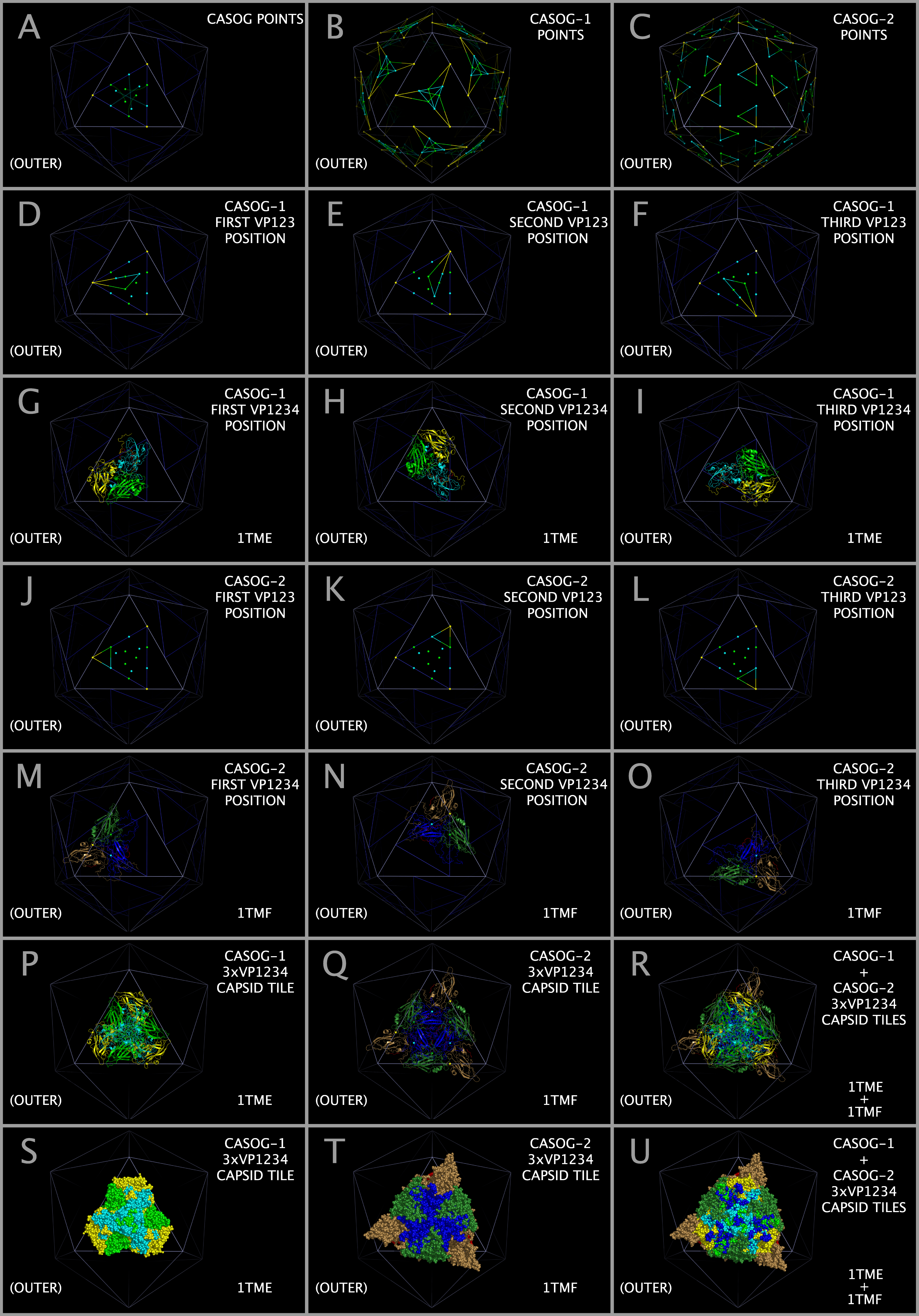 |
| Access PDF version of image in new browser window. |
Figure 5. Model picornavirus capsid construction for the CASOG-1 and CASOG-2 proteins.
Figure 5 illustrates the method of superposing the X-ray structures of picornavirus CASOG-1 and CASOG-2 VP1-VP2-VP3-VP4 protein assemblies (“VP1234”)
onto an icosahedron to form model virus capsid tiling pieces. The VP1234 assemblies are placed on the icosahedral face using conserved prolines.
The vertices of the TRI78 triangles are points that represent positions of conserved VP3 proline atoms in both CASOG-1 and CASOG-2 picornavirus capsids.
The VP3 proline atom is both sequence and spatially invariant. The TRI78 triangles are colored dark blue.
Capsid tiling points are colored cyan for VP1, green for VP2, yellow for VP3, and magenta for VP4.
Panel A shows both CASOG-1 and CASOG-2 tiling points on and within a single TRI78 triangle. Dashed lines indicate the difference in the position of atoms (either from VP1 or VP2) between CASOG-1 and CASOG-2.
Panel B shows the destination points for the individual CASOG-1 VP1, VP2, and VP3 atoms listed in Table 3.
Panel C shows the destination points for the individual CASOG-2 VP1, VP2, and VP3 atoms listed in Table 4.
Panels D — F show the three mapping positions for CASOG-1 VP1234.
Panels G — I show examples (TMEV-1 cartoons) of CASOG-1 VP1234 in these positions.
Panels J — L show the three mapping positions for CASOG-2 VP1234.
Panels M — O show examples (TMEV-2 cartoons) of CASOG-2 VP1234 in these positions.
Panel P shows these three VP1234 positioned together as a CASOG-1 capsid tiling piece (TMEV-1 cartoons) and Panel S shows the same capsid tiling piece as spheres.
Panel Q shows these three VP1234 positioned together as a CASOG-2 capsid tiling piece (TMEV-2 cartoons) and Panel T shows the same capsid tiling piece as spheres.
Panel R shows the overlap of Panels P and Q. Panel U shows the overlap of Panels S and T.
Figure 6. Comparison of constructed CASOG-1 and CASOG-2 picornavirus capsid tiling piece pentamers.
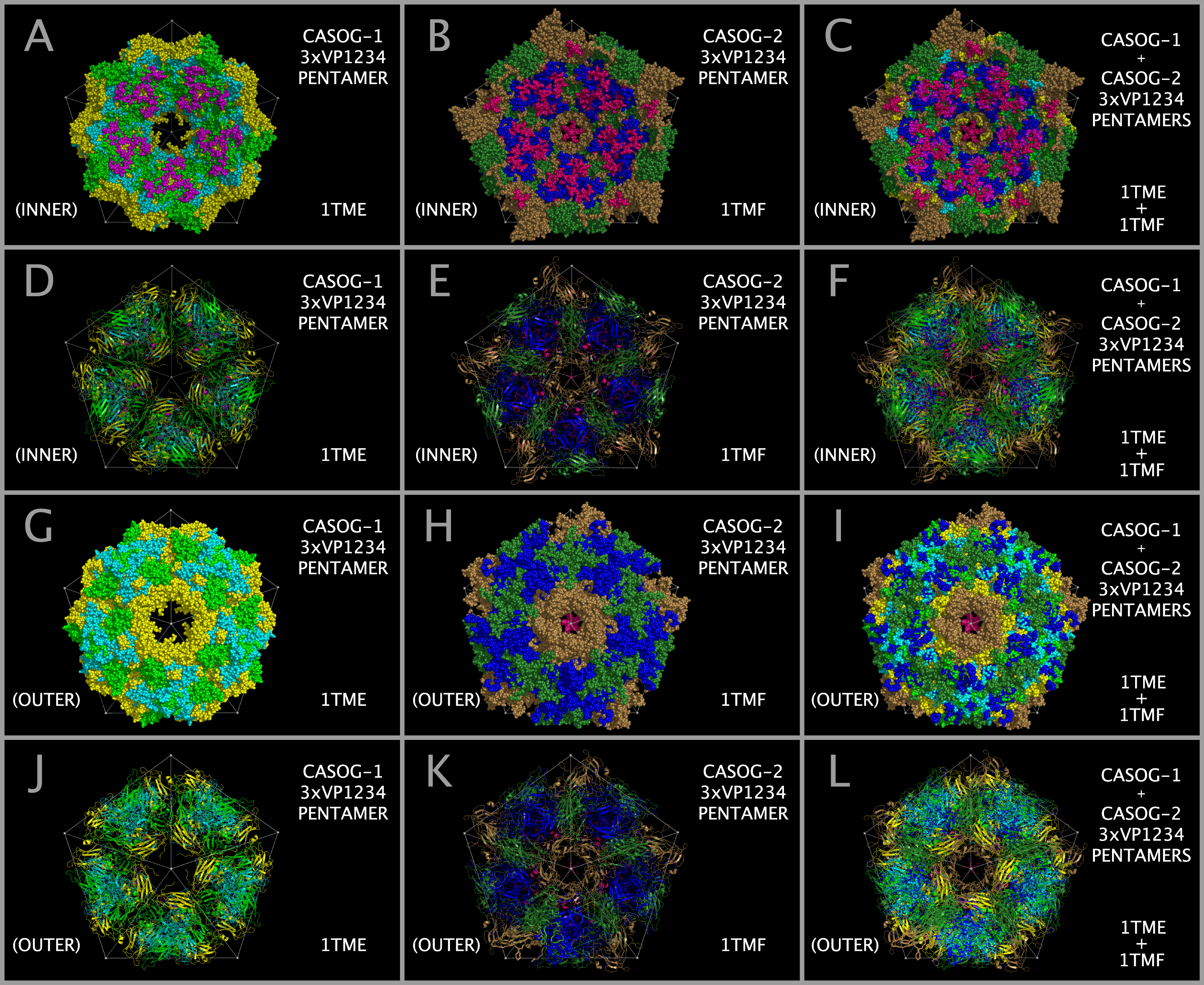 |
| Access PDF version of image in new browser window. |
Figure 6. Comparison of constructed CASOG-1 and CASOG-2 picornavirus capsid tiling piece pentamers. Figure 6 (previous page). Comparison of constructed CASOG-1 and CASOG-2 picornavirus capsid tiling piece pentamers. Figure 6 shows the constructed capsid tiling piece pentamers for TMEV-1 (1TME.PDB) and TMEV-2 (1TMF.PDB), which are nearly identical in sequence. All Figure 6 Panels show ICOS135 points connected with white lines as a reference to the rest of the capsid. TMEV-1 VP1 proteins are shown in cyan, TMEV-1 VP2 proteins are shown in bright green, TMEV-1 VP3 proteins are shown in yellow, TMEV-2 VP1 proteins are shown in dark blue, TMEV-2 VP2 proteins are shown in dark green, TMEV-2 VP3 proteins are shown in tan. TMEV-1 and TMEV-2 VP4 proteins are shown in magenta. Pentamers of TMEV-1 3xVP1234 capsid tiling pieces are shown in the first column (Panels A, D, G, and J). Pentamers of TMEV-2 3xVP1234 capsid tiling pieces are shown in the second column (Panels B, E, H, and K). The last column (Panels C, F, I, and L) show the superposition of the first two columns. Panels A — F show the inner (RNA side) capsid face. Panels G — L show the outer (cellular side) capsid face. Panels D — F and J — L show structure cartoons. Panels A — C and G — I show protein residues as spheres.
Figure 7. Construction of myelin P2 trimers, CRABP trimers, and Alpha-bungarotoxin Trimers.
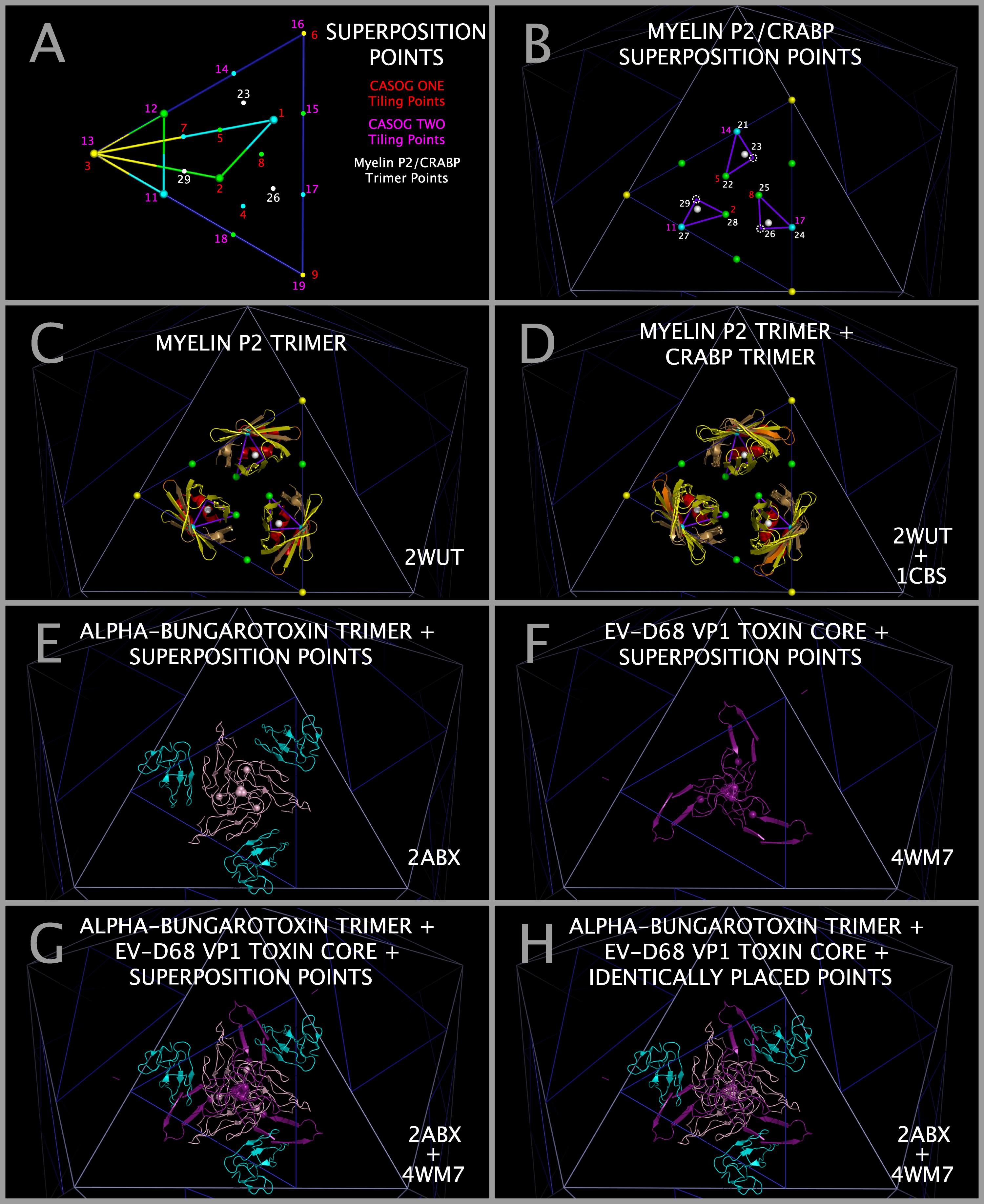 |
| Access PDF version of image in new browser window. |
Figure 7. Construction of myelin P2 trimers, CRABP trimers, and Alpha-bungarotoxin Trimers. Figure 7 illustrates the construction of myelin P2 trimers, CRABP trimers, and alpha-bungarotoxin trimers. Figure 7 Panel A shows the relationship between CASOG-1 and CASOG-2 tiling points and additional myelin P2 and CRABP tiling points. Figure 7 Panel B shows the superposition points for the myelin P2 and CRABP atoms: six of the superposition points are from the CASOG-1 and CASOG-2 tiling points and three points are added (white dashed circles) to create a complete set of nine destination points for three myelin P2 and three CRABP monomers. Figure 7 Panel C shows a Myelin P2 trimer positioned on an icosahedron face. Figure 7 Panel D shows co-located Myelin P2 and CRABP trimers positioned on an icosahedron face. Figure 7 Panel E shows cartoons of a trimer of ABT dimers in its superposed position on EV-D68-4WM7 VP1 trimer atoms with the ABT Table 6 atoms as spheres, the ABT chain A cartoon colored violet and the ABT chain B cartoons colored teal. Figure 7 Panel F shows cartoons of the purple EV-D68 VP1 trimer Toxin Section Residues and the EV-D68 VP1 Table 6 atoms as spheres. Figure 7 Panel G shows cartoons of a trimer of ABT in its superposed position, the EV-D68 VP1 trimer Toxin Section Residues overlapping the corresponding ABT A chain cartoon, and all of the Table 6 atoms as spheres. Figure 7 Panel H shows: the perfect overlap at the center of the trimers of ABT atom 91 with EV-D68 atom 1414; and ABT atom 96 with EV-D68 atom 1412 which can be used as an additional check on positioning the ABT trimer.
Figure 8. Myelin P2, CRABP, and Picornavirus Myelin P2/CRABP Cores.
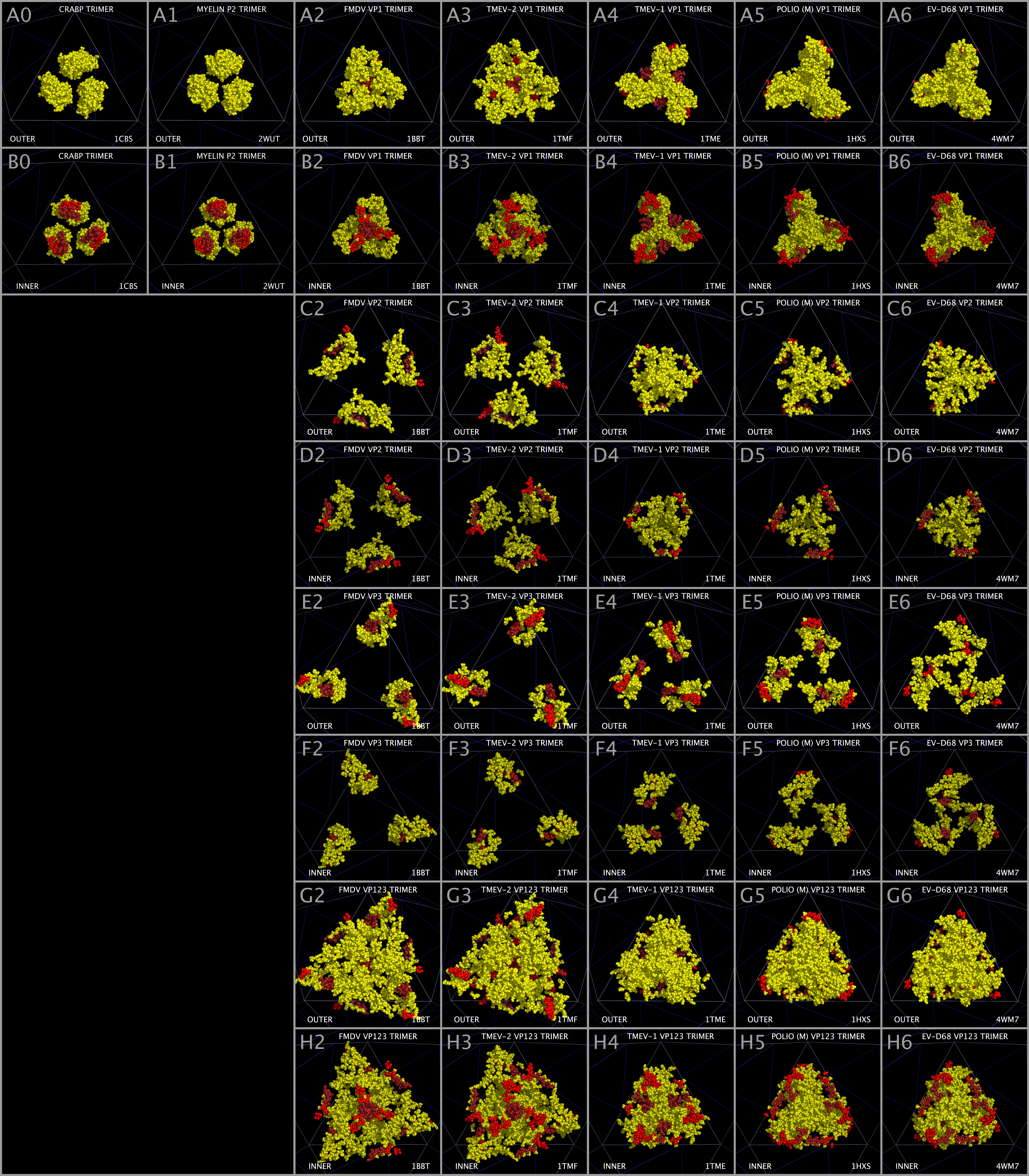 |
| Access PDF version of image in new browser window. |
Figure 8. Myelin P2, CRABP, and Picornavirus Myelin P2/CRABP Cores. Figure 8 shows Myelin P2/CRABP Core residues in trimers of: CRAPB (Panels A0 and B0); myelin P2 (Panels A1 and B1); FMDV VP1 (Panels A2 and B2); TMEV-2 VP1 (Panels A3 and B3); TMEV-1 VP1 (Panels A4 and B4); PV1 (POLIO) VP1 (Panels A5 and B5); EV-D68 VP1 (Panels A6 and B6); FMDV VP2 (Panels C2 and D2); TMEV-2 VP2 (Panels C3 and D3); TMEV-1 VP2 (Panels C4 and D4); PV1 (POLIO) VP2 (Panels C5 and D5); EV-D68 VP2 (Panels C6 and D6); FMDV VP3 (Panels E2 and F2); TMEV-2 VP3 (Panels E3 and F3); TMEV-1 VP3 (Panels E4 and F4); PV1 (POLIO) VP3 (Panels E5 and F5); EV-D68 VP3 (Panels E6 and F6); FMDV VP123 (Panels G2 and H2); TMEV-2 VP123 (Panels G3 and H3); TMEV-1 VP123 (Panels G4 and H4); PV1 (POLIO) VP123 (Panels G5 and H5); and EV-D68 VP123 (Panels G6 and H6). Myelin P2 Core residues in Figure 8 are colored yellow with the exception of Figure 1 Section M-2 to I123-2 which are colored red and Section M-4 residues which are colored dark red to highlight the positions of the individual helices relative to each other and to the rest of the Myelin P2/CRABP Core residues in each panel.
Figure 9. Myelin P2 trimers, Alpha-bungarotoxin trimers, Picornavirus Myelin P2/CRABP Cores, and Picornavirus Toxin Cores.
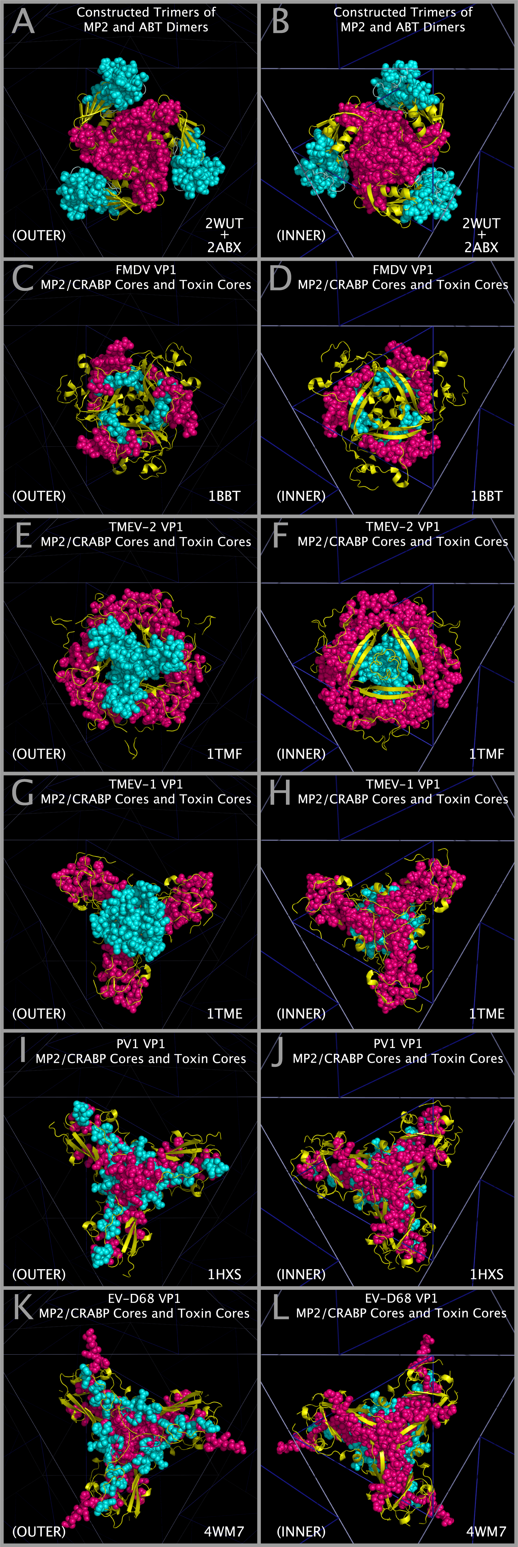 |
| Access PDF version of image in new browser window. |
Figure 9. Myelin P2 trimers, Alpha-bungarotoxin trimers, Picornavirus Myelin P2/CRABP Cores, and Picornavirus Toxin Cores. Figure 9 shows the relationship between: a) constructed Myelin P2 trimers and trimers of alpha-bungarotoxin dimers; and b) selected picornavirus VP1 Myelin P2/CRABP Cores and Toxin Cores. Myelin P2 and VP1 Myelin P2/CRABP Cores cartoons are colored yellow. Alpha-bungarotoxin A chain trimer residue spheres are colored dark magenta. FMDV, TMEV-1, TMEV-2, PV1, and EV-D68 VP1 Toxin Core residue spheres for residues in Figure 1 Sections A-1 to A-6 (corresponding to ABT chain A) are colored dark magenta. Alpha-bungarotoxin B chain trimer residues 1 — 48 residue spheres are colored cyan. FMDV, TMEV-1, TMEV-2, PV1, and E-D68 VP1 Toxin Core residue spheres for residues in Figure 1 Sections B-1 to B-5 (corresponding to ABT chain B residues 1 — 48) are colored cyan. Alpha-bungarotoxin B chain trimer residues 49 — 74 are shown as a light cyan cartoon for reference. Panels A and B show cartoons of Myelin P2 trimers, cartoons of alpha-bungarotoxin B chain residues 49 — 74; and residue spheres of trimers of alpha-bungarotoxin A Chains and trimers of alpha-bungarotoxin B Chain residues 1 — 48. VP1 Myelin P2/CRABP Core (Figure 1 M-1 to M-16) cartoons and VP1 Toxin Core residue spheres (Figure 1 A-1 to A-6 and B-1 to B-5) for: FMDV are shown in Panels C and D; TMEV-2 are shown in Panels E and F; TMEV-1 are shown in Panels G and H; PV1 are shown in Panels I and J; and EV-D68 are shown in Panels K and L.
Figure 10. Toxin Domain Structure in Alpha-bungarotoxin and EV-D68.
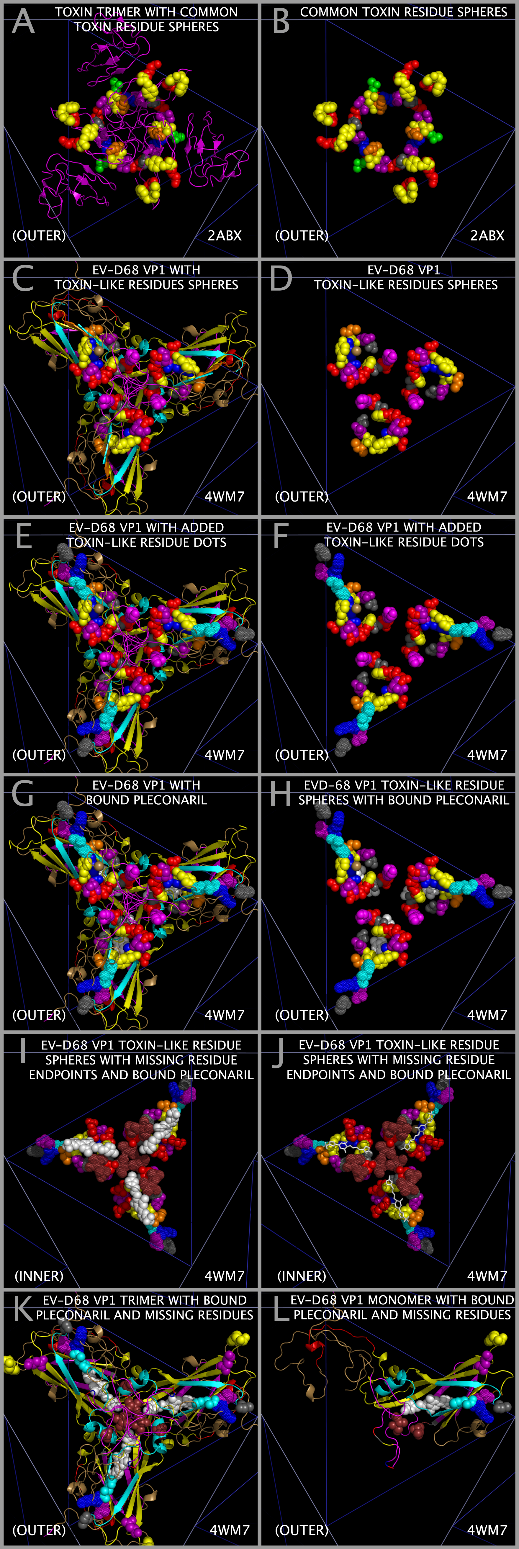 |
| Access PDF version of image in new browser window. |
Figure 10. Toxin Domain Structure in Alpha-bungarotoxin and EV-D68. Figure 10 shows the TOX DOMAIN presentation in trimers of alpha-bungarotoxin dimers and EV-D68-4WM7 VP1 trimers with two VP2 residues shown. In Figure 10, residue spheres and dots are colored: D/E - red; R/K - blue; H - cyan; S/T - green; N/Q - purple; A - light grey; G - grey; P - black; I/V/L/F - yellow; Y - tan; and C/W/M - orange. Plecornaril spheres and sticks are colored white. Figure 10 panel A shows purple cartoons of constructed trimers of alpha-bungarotoxin (ABT) trimers. Figure 10 panels A and B show the toxin loop residue spheres for the A chain of ABT: G19-E20-N21-L22-C23 (Figure 1 Section A-1 ); T62-D63-K64-N66 (Figure 1 Section A-4); D30-A31-F32 (Figure 1 Section A-1); and Y54-E55-E56 (Figure 1 Section A-3). In Figure 10 Panels A and B, the ABT chain A residues E20-N21 and D63-K64-N66 form an annulus of complimentary charge and the Y54 and F32 rings are close enough to contact each other and add additional stability to the annulus structure. Figure 10 panels C, E, G, K, and L show the EV-D68 VP1 trimer cartoon colored as in the Figure 1 Section header for spatial reference. Panels C, D, E, F, H, I, and J show EV-D68 residue spheres and dots specified in Figure 1: VP1 Section I1-2 Subsection 3 residues-HKN (non-pathogenic sequence in 4WM7.PDB where TOXLOOP1 would be present in pathogenic EV-D68 —shown as dots); VP1 Section A1 residues DGF (“TOXLOOP2” — shown as spheres); VP1 Section A2 residues GNLC (“TOXLOOP3” —shown as spheres); and VP2 Section A-3 Subsection 2 residues (“TOXLOOP4” —shown as spheres). To demarcate the position of missing residues in the 4WM7.PDB structure, A80 (grey), H87 (cyan), K88 (blue), and N89 (purple) are represented by dots in Panels E, F, H, I, and J; residues G210, I211, T217, and I218 in Panels I and J are shown by brown dots; and residues I211 and T217 are represented by brown spheres in Panels K and L. In panels G, H, I , J, K, and L, plecornaril is represented by white spheres or sticks.
Figure 11. Sialic Acid Binding Domain Components on EV-D68 Capsid.
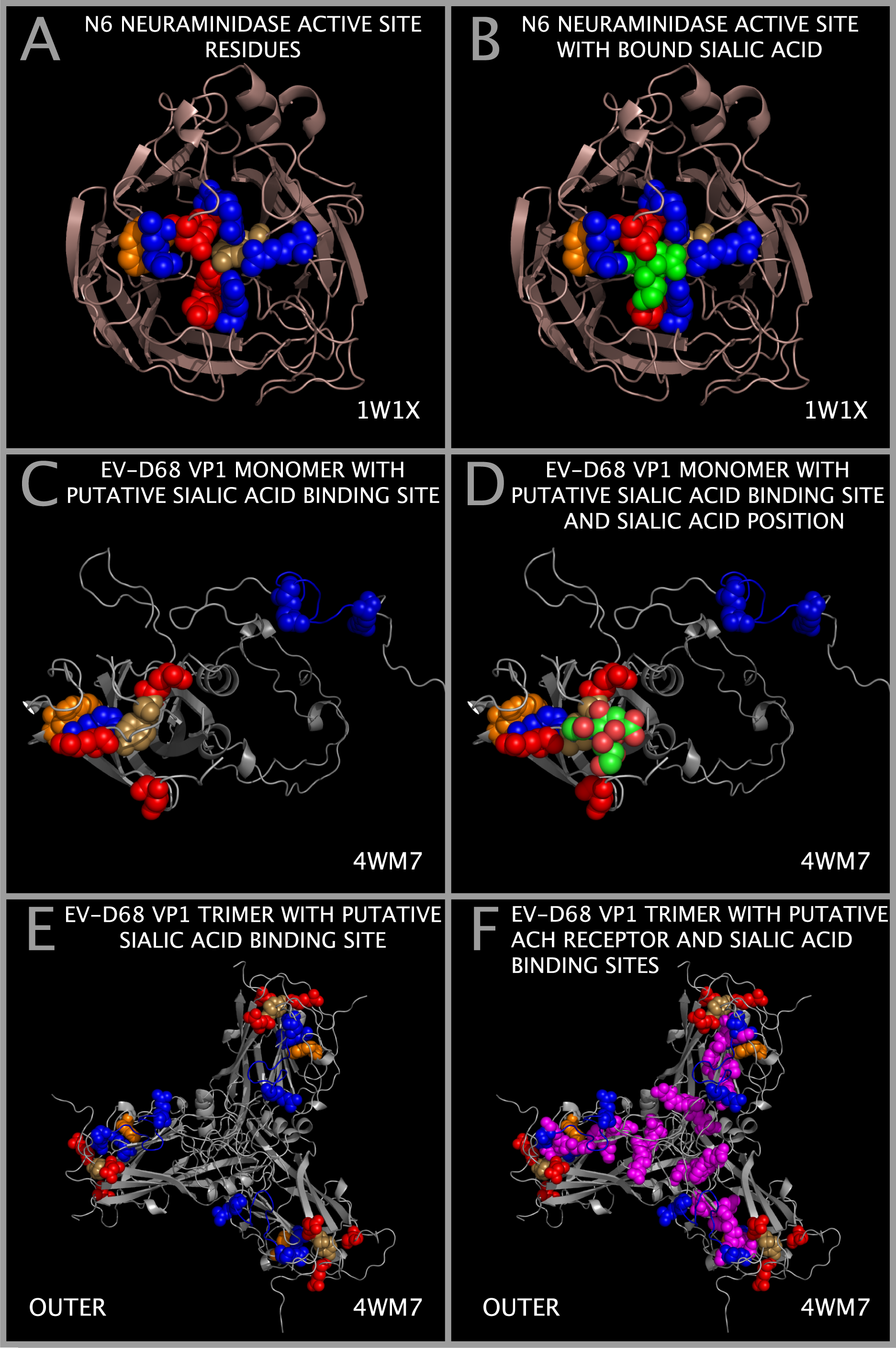 |
| Access PDF version of image in new browser window. |
Figure 11. Sialic Acid Binding Domain Components on EV-D68 Capsid. Figure 11 Panel A shows the influenza N6 neuraminidase [49] cartoon and residue spheres of: Y412 (tan), D157 (red), R124 (cyan), G227 (red), R158 (cyan), R 299 (cyan), and W185 (orange). Figure 11 Panel B adds green residue spheres of sialic acid to Panel A. Figure 11 Panel C shows a cartoon of EV-D68 VP1 and spheres for residues that we have identified in the Figure 1 row labelled “SUBSECTION DESCRIPTOR MARKER” with the subsection title suffix “-SW” (i.e., E75 (red, Figure 1 Section I13-1), Y76 (yellow, Figure 1 Section I13-1), D140 (red, Figure 1 Section M-8), W163 (orange, Figure 1 Section M-12), R223 (blue, Figure 1 Section A-2), E227 (red, Figure 1 Section M-13), R270 (blue, Figure 1 Section I1-5), and R284 (blue, Figure 1 Section M-16) residues). Panel C residues are also identified in Figure 2 in the row labelled “SIA BINDING SITE COMPONENT POSTION (WEININGER)”. Figure 11 Panel D adds a model built sialic acid (green carbons, red oxygens, and blue nitrogen atom spheres) to the partial, putative sialic acid binding site shown in Panel C. Figure 11 Panel E shows a trimer of putative sialic acid binding sites formed by a trimer of VP1 proteins shown as monomers in Panel C. Figure 11 Panel F adds to Panel E the residue spheres comprising the toxin domain in EV-D68, the residues of which are identified in Figure 2 in the row labelled “EV-D68 (PATHOGENIC) CAPSID TOXIN-LIKE LOOP RESIDUES”.
Figure 12. Differences in the spatial position of markers in constructed TMEV capsid tiling pieces and capsids.
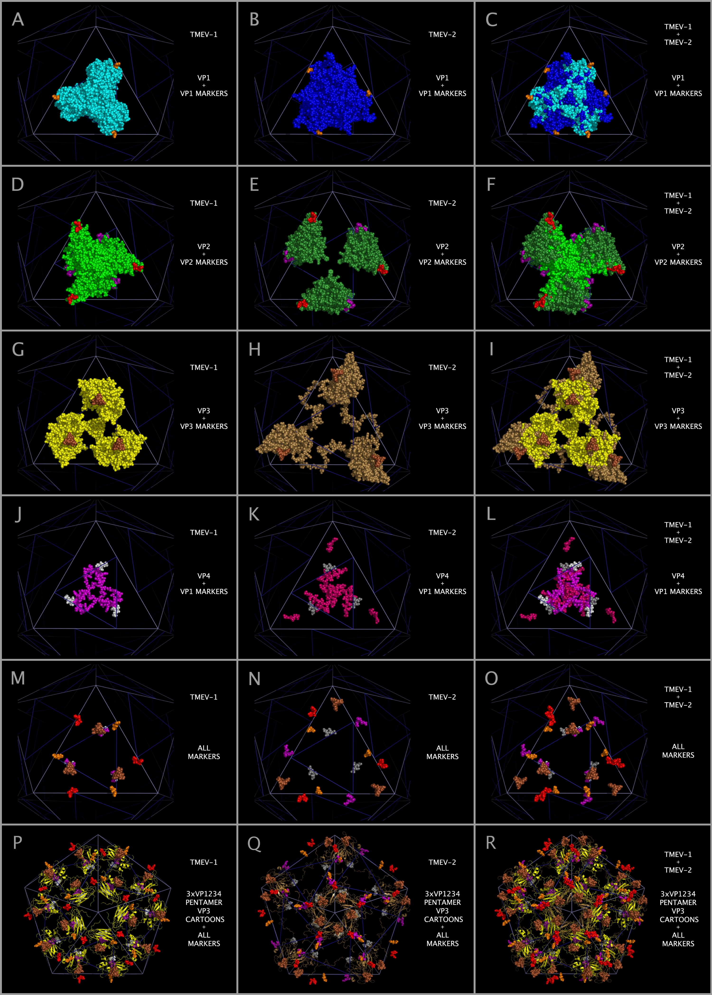 |
| Access PDF version of image in new browser window. |
Figure 12. Differences in the spatial position of markers in constructed TMEV capsid tiling pieces and capsids.
Figure 12 shows the differences in the spatial position of corresponding residue markers in the constructed TMEV-1 and TMEV-2 Capsids.
All markers are shown in the Figure 1 headers under the Subsection title suffix “-M”.
Panel A shows TMEV-1 VP1 protein spheres (cyan) with orange Y161-T162 residue marker spheres.
Panel B shows TMEV-2 VP1 protein spheres (dark blue) with orange Y163-T164 residue marker spheres.
Panel C shows the superposition of Panels A and B.
Panel D shows TMEV-1 VP2 protein spheres (bright green) with purple R260-H261-E262 and red Y235-A236-S237 residue marker spheres.
Panel E shows TMEV-2 VP2 protein spheres (dark green) with purple R260-H261-E262 and red Y235-A236-T237 residue marker spheres.
Panel F shows the superposition of Panels D and E.
Panel G shows TMEV-1 VP3 protein spheres (yellow) with dark brown N58-S59-N60-N61-K62-R63-Y64 residue marker spheres.
Panel H shows TMEV-2 VP3 protein spheres (tan) with dark brown N58-T59-N60-N61-K62-R63-Y64 residue marker spheres.
Panel I shows the superposition of Panels G and H.
Panel J shows TMEV-1 VP4 protein spheres (magenta) and TMEV-1 VP1 S11-N12-D13-D14 white marker spheres.
Panel K shows TMEV-2 VP4 protein spheres (dark pink) and TMEV-2 VP1 S11-N12-D13-D14: grey marker spheres.
Panel L shows the superposition of Panels J and K.
Panel M shows all of the TMEV-1 marker spheres.
Panel N shows all of the TMEV-2 marker spheres.
Panel O shows the superposition of Panels M and N.
Panel P shows TMEV-1 3xVP1234 pentamer VP3 structure cartoons (in yellow) and the TMEV-1 marker spheres.
Panel Q shows TMEV-2 3xVP1234 pentamer VP3 structure cartoons (in tan) and the TMEV-2 marker spheres.
Panel R shows the superposition between Panels P and Q.
Figure 13. VP3 Protein Beta Sheets Circling The Pentamer Interface Form The Base Of A Diaphragm Shutter-like Pore.
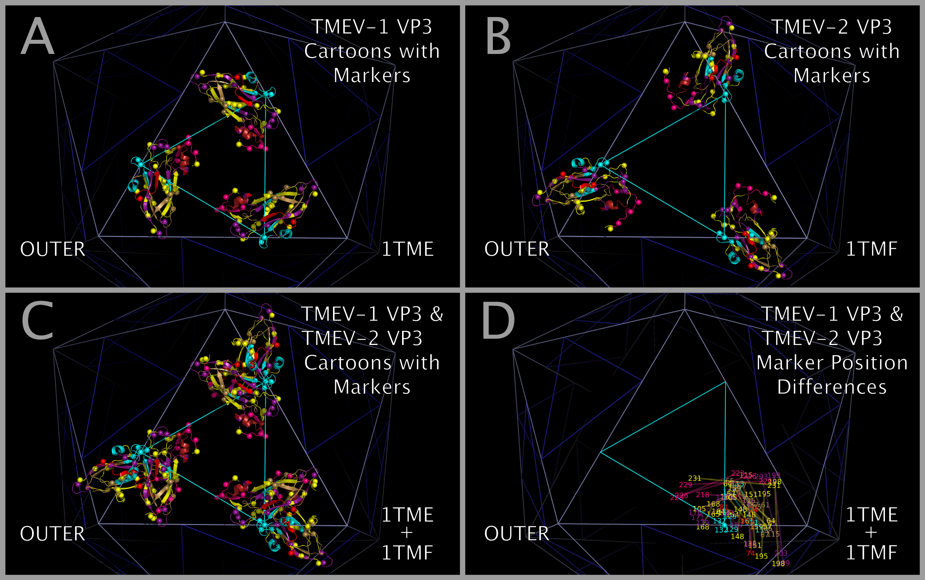 |
| Access PDF version of image in new browser window. |
Figure 13. VP3 Protein Beta Sheets Circling The Pentamer Interface Form The Base Of A Diaphragm Shutter-like Pore. Figure 13 panels A, B, and C show TMEV-1 and/or TMEV-2 structure cartoons with their proline residue main chain oxygen atoms as spheres. Panel D shows lines between sequence equivalent prolines in TMEV-1 and TMEV-2 along with the residue number of the matching prolines.
Figure 14. Using Insert Residue Positions To Isolate Variations in Relative Position of Aligned Structures.
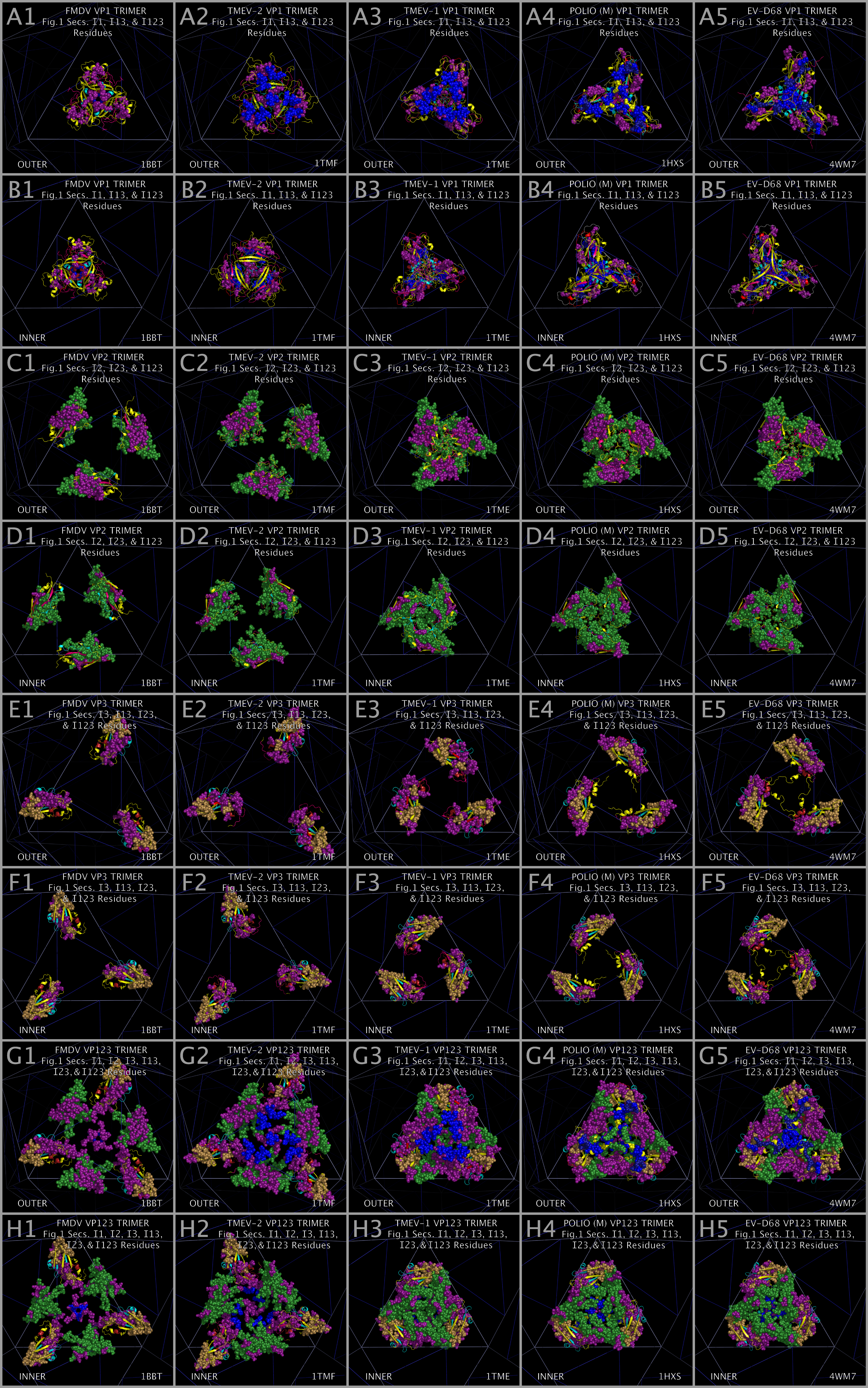 |
| Access PDF version of image in new browser window. |
Figure 14. Using Insert Residue Positions To Isolate Variations in Relative Position of Aligned Structures. Figure 14 Panels A1 — A5 and Panels B1 — B5 show Insert residues for the VP1 trimers colored according to their Figure 1 Section color. Figure 1 Panels C1 — C5 and Panels D1 — D5 show Insert residues for the VP2 trimers colored according to their Figure 1 Section color. Figure 1 Panels E1 — E5 and Panels F1 — F5 show Insert residues for the VP3 trimers colored according to their Figure 1 Section color. Figure 14 Panels G1 — G5 and H1 — H5 show superposed composites of VP1, VP2, and VP3 trimer Inserts.
Figure 15. Ion channel-like structure in the center of myelin P2 trimers and VP1 trimers.
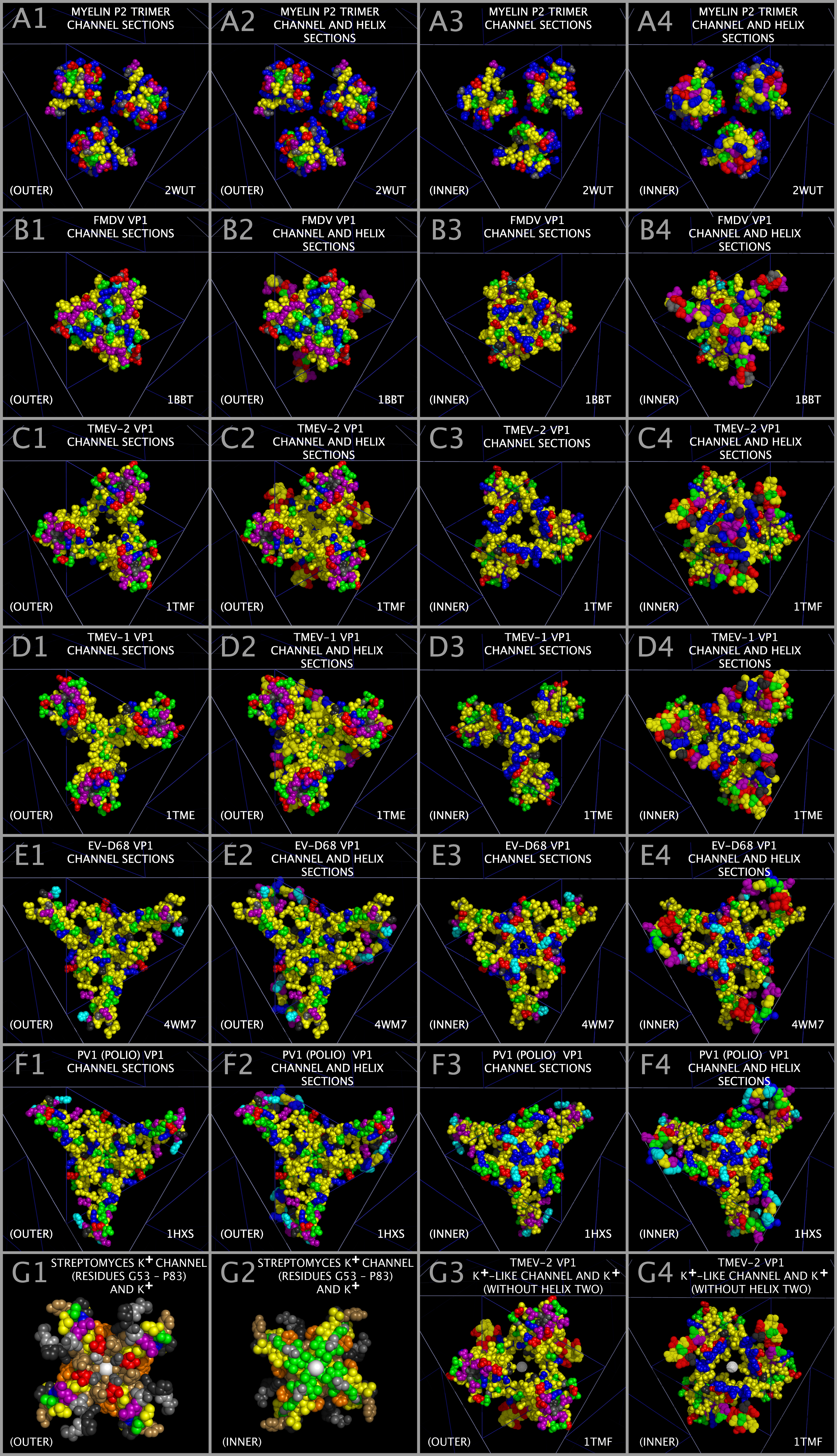 |
| Access PDF version of image in new browser window. |
Figure 15. Ion channel-like structure in the center of myelin P2 trimers and VP1 trimers. Figure 15 shows the Figure 1 Sections M-2 to M-4 (“Helices”) residues and Sections M-5, M-6 to M-10, M-13, and M-14 (“Channel”) residues of myelin P2 trimer (Panels A1 — A4) and the VP1 trimers of FMDV (Panels B1 — B4), TMEV-2 (Panels C1 — C4, G3, and G4), TMEV-1 (Panels D1 — D4), EV-D68 (Panels E1 — E4), and PV1 (Panels F1 — F4). Panels A1, B1, C1, D1, E1, F1, A3, B3, C3, D3, E3, F3, and G3 contain Channel Residues (spheres) but no Helices residues. Panels A2, B2, C2, D2, E2, F2, A4, B4, C4, D4, E4, F4, and G4 contain Helices Residue (dots) and Channel Residues (spheres). Figure 15 Panels G1 and G2 show the residue spheres of a tetramer of Streptomyces lividans (“K-ION-CHANNEL”) for residues G53 to P83. Figure 15 Panels G1 — G4 also show a potassium ion as a white sphere. The position of the potassium ion in Panels G1 and G2 are from the X-ray crystal structure 1BL8.PDB and the position of the potassium ion in Panels G1 and G2 is model built. The residue dots and spheres in Figure 15 are colored yellow with the exceptions that the residues D, E, R, K, H, S, T, N, Q, G, and P are colored as in Figure 1 columns: D/E - red; R/K - blue; H - cyan; S/T - green; N/Q - purple; G - grey; P - black; and potassium ion - white. Panels in the first column of Figure 15 (A1, B1, C1, D1, E1, and F1) and Panels in the second column of Figure 15 (A2, B2, C2, D2, E2, and F2) show the Outer view. Panels in the third column of Figure 15 (A3, B3, C3, D3, E3, and F3) and Panels in the fourth column of Figure 15 (A4, B4, C4, D4, E4, and F4) show the Inner view. Figure 15 Panels G1 and G2 show a tetramer of Streptomyces lividans (“K-ION-CHANNEL”) for residues G53 to P83.